
66xx part 1
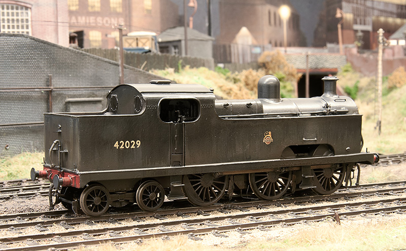
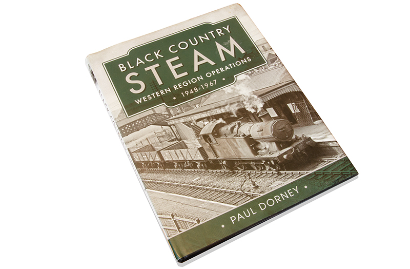 For a while now Ive had this book (which I highly recommend by the way) featuring 6683 passing the real Brettell lane on its cover. Recently I stumbled upon a pretty cheap Bachmann 56xx body on ebay and realising that High Level Kits do a chassis for it another project, that if I’m honest I really don’t need as I have enough locos anyway) has found its way onto the workbench.
56xx and 66xx – A super brief history
After world war 1 many of the locomotives that served Welsh railway companies were in very poor state. Most of the Welsh companies saw the GWR as a competitor and resented them taking over, so given they were going out of business anyway they spent very little on maintenance and overhauls. Charles Collett needed a fleet of new locos for the Welsh coal traffic, the 42xx 2-8-0s were too wide at a number of locations due to their outside cylinders. Thus the 56xx tank engines were ordered from Swindon, the last 50 locos would be built by Armstrong Whitworth of Newcastle-upon-Tyne.
The class didn’t get off to the greatest of starts when class pioneer 5600 was rolled out in front of all the works bigwigs and promptly failed on its first movement due to a flaw in the design of the inside motion. With 50 locos already under construction and to avoid embarassment to both the designers and the GWR it was all hushed up with the staff sworn to secrecy and the revised drawings for the valve gear back dated to look like they were the originals.
Not long after they were introduced the depression hit the UK and half of the pits in South Wales closed. The GWR had gone from not having enough 0-6-2 locos to having too many!
By 1960 they were no longer a south wales loco exclusively. Locally to me Stourbridge Shed had 7 of them and Tysley 3.
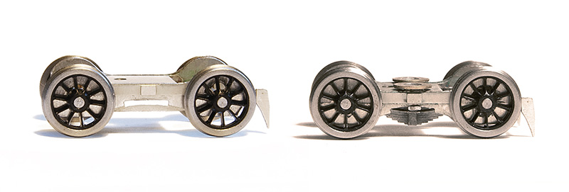
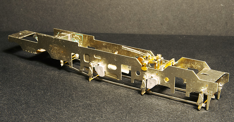
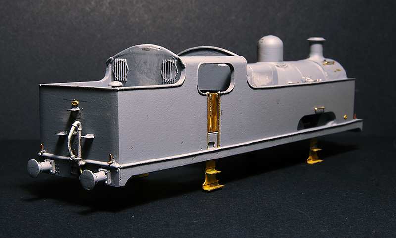
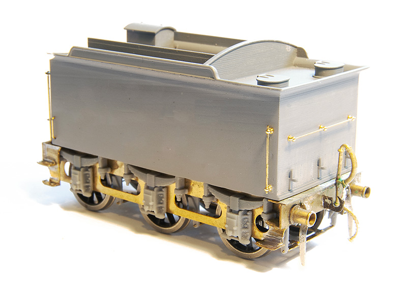
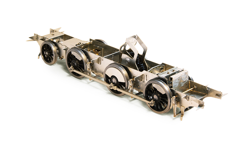 So the High Level Kits chassis. which accommodates the Swindon and Armstrong Whitworh builds Built as designed by Chris. I didn’t go my usual route of complicating things by fitting working inside motion as you really cant see it plus Chris has powered the middle axle. The rear axle and trailing truck work together as part of the suspension. Theres a representation of the slide bars etc in the kit
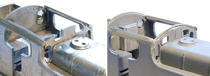
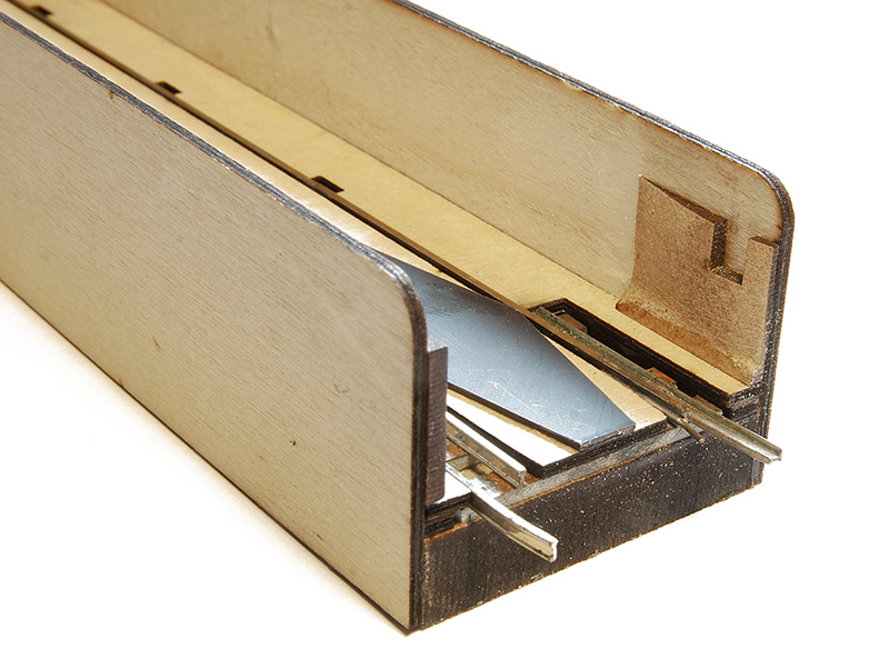
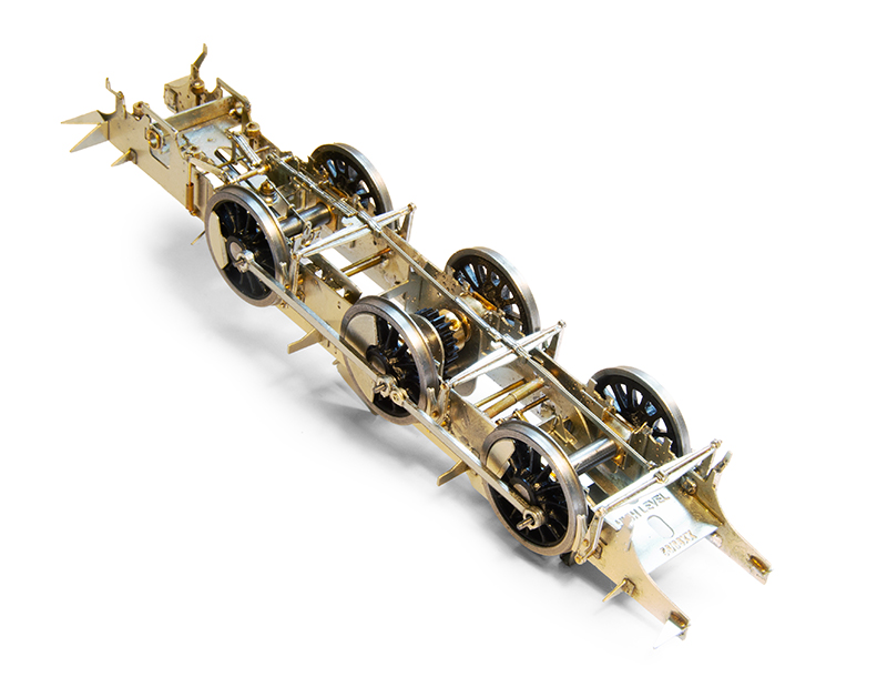 Underside. The brake gear is designed to be removable. I will fit the representations of the springs after its all painted and tested.
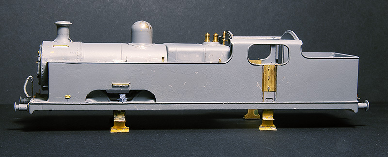
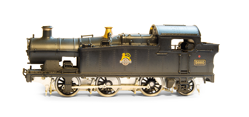 Test fit of the body, which I will move onto in Part 2
lurking around the station.
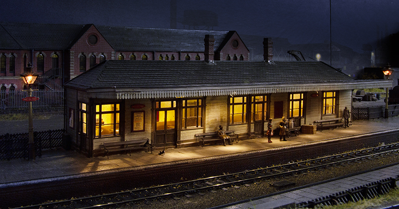
Just a short post this time. A request on a facebook group for pictures of stations led me to realise I’ve never raken a picture of the main station building with the completed background behind it. So…
Ive had a little fiddle to add headlights to my GWR angled railcar as it never had them before. I also realised I’d never added any lamp irons to it either so thats sorted as well. 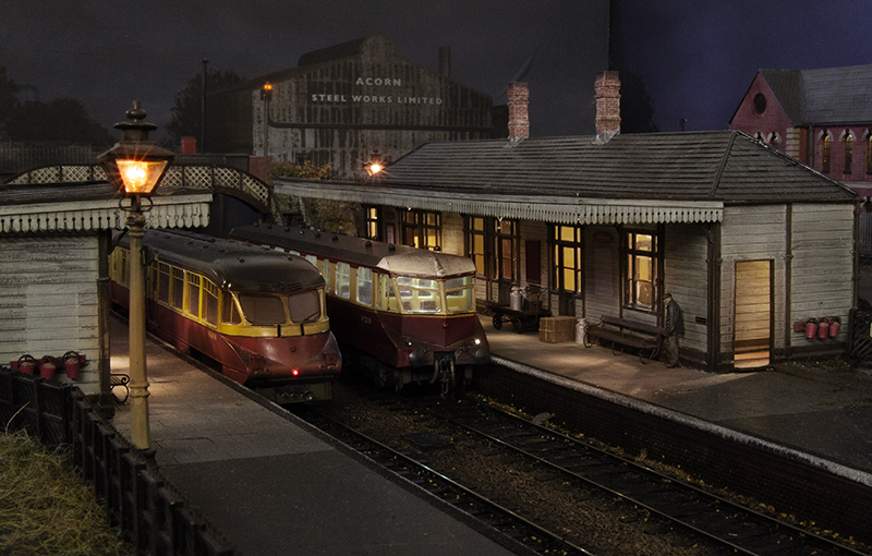
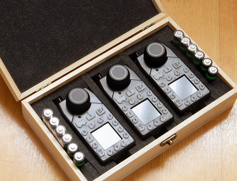
Finally as a follow on to the last post I’ve made a little box for my handsets (when I say made I mean brought a wooden box from Amazon and added some foam to it!)
Goings on behind the scenes
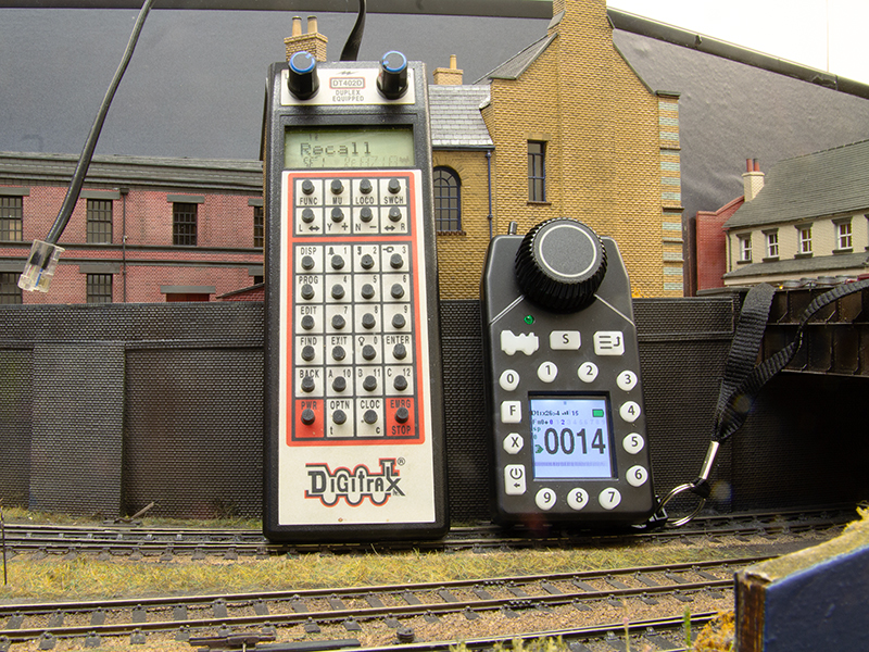 At Macclesfield the chaps from WFRM kindly let me borrow one of their Digitrax UT6 utility throttles and I was very quickly sold on the idea of them (Thanks again guys). On the left one of the DT402 throttles I was using and the UT6 is on the right. The 402 has 2 throttles per handset and while this is a good thing, in the reality of an exhibition you don’t really use them much and if you do you can easily end up driving the wrong loco. The other thing about the 4o2 is after a while the buttons get a bit sticky and they use 9v batteries which these days are not cheap. I found that one battery would last 1 day, roughly speaking, per throttle. The guys at WFRM confidently say that the 3 AA’s the UT6 uses will happily last a whole exhibition. I’ll find out at Stafford in September. The UT6 fits nicely in the hand and comes with a lanyard so you don’t drop them, yes I have dropped the DT402’s in the past – thankfully without damage! You can’t do everything on the UT6 that you can on the DT402, so they aren’t completely redundant but you can do everything you would expect to have to do at an exhibition.
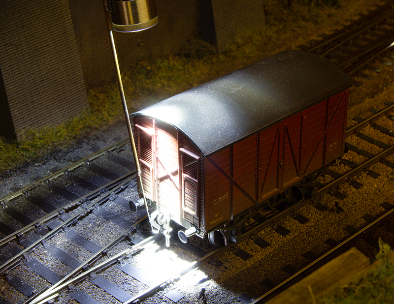
Remember my thoughts on uncoupling in the dark? No? Well you can have a refresh here if you want to.
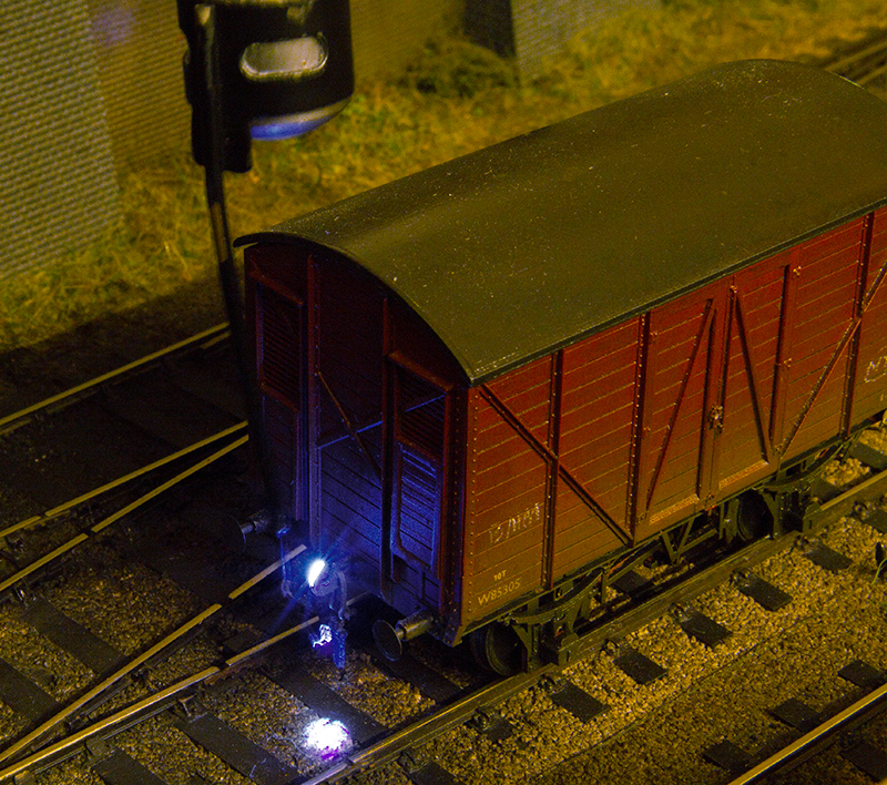 I ended up using a somewhat expensive laser UV torch which worked quite well if everything was set up perfectly. In reality though, because the light is so small, one slight ding on the coupling hook and you couldn’t see it anymore to pick up the links. Also the eye strain over 2 days was quite noticeable. Phil never really got on with it and I found myself reverting to the much cheaper pen torches that I also took along to shows.
 A lot of talk is had on forums and social media groups of the “hand of god” and how unrealistic it is. However experience shows that people are generally quite fascinated by the coupling up process. I wonder if it’s because of the darkness? I still feel that the cheapo pen torches chuck out too much light though and given that when operating (and viewing the layout hopefully) your eyes adjust to the gloom it can take a moment to re-adjust back after coupling something up.
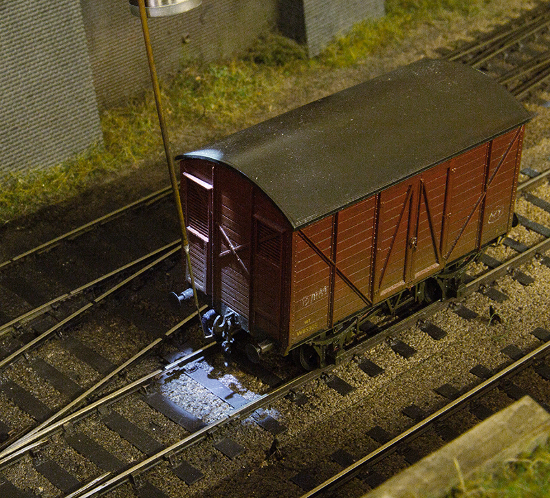 The low tec’ solution is a simple rubber washer and a 2mm brass washer to drop the intensity and size of the light down. Again Stafford exhibition will be a test for the new approach.
Macclesfeild Show
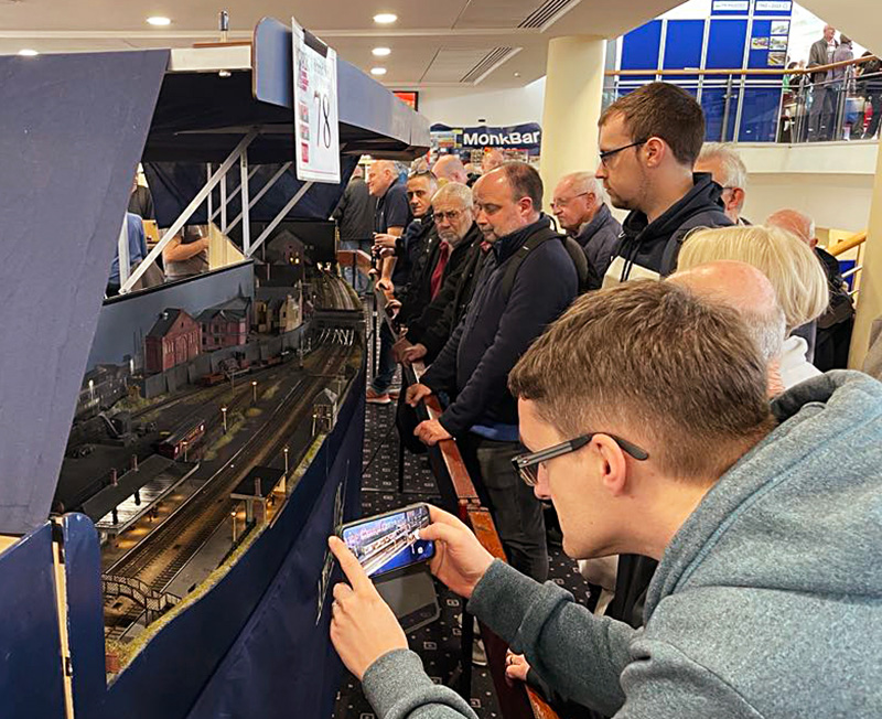
 Last weekend we had a great outing to the Macclesfield Show with Brettell Road. A good time was had by all and the layout performed very well. Above picture ©Tim Horn and used with permission.
Tim also did a great little video of the layout for which I send my thanks. As always thanks to all of the guys for their efforts over the weekend.
As always theres a list of things to do but I think it’s fair to say these are tweaks and improvements rather than dramatic changes. Theres a small rake of wagons that need looking at as well as a few locos. I think it’s just a fact of taking layouts to shows that these will always come up. Bouncing stock around in a vehicle isn’t the best way to care for it, especially with the roads in the UK being the state they currently are.
One of the vees under the bridge (of coarse it is) might be dead. I will need to investigate. Because most stock could straddle it at the show and all the steam locos have stay alives fitted it wasn’t something that affected the running. Who knows, if it is dead, it might have been so for a while and I just didn’t notice! Also one of the short protectors played up. The layout is fed from the middle and the DCC power is split either side of this into 3 districts. One for the yard, one for the mainline and one for operating things like points and signals. The one for the yard on the right (as you look at the layout) was still providing short protection but it wasn’t resetting meaning we needed a couple of times to cycle the track power off and on again. I had a spare board with me but like the vee it wasn’t enough of a problem to worry about at the show. It’s been swapped now.
Simon spotted there was a height difference of about 1mm between the Dudley scenic end and the fiddleyard so I will look at that and we managed to scratch the paint on the fiddleyard front loading it into the van. Ive already repainted it but i will rotate the carrying handles so that its naturally always the right way up in the future.
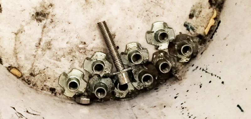 Finally a recurring problem. At the first show we did with the layout in its current form some of the captive nuts that are used to hold the roof uprights in place bound up and we couldn’t get the uprights off. Since then I ran a tap through them and they have been fine but last weekend one bound up again. Luckily the design of the uprights meant they could be taken apart and the offending upright taped to the board to be dealt with at home. The captive nuts have been relocated to the bin and I will use wingnuts going forward.
Looking East
Ive seen this picture pop up a couple of times on facebook groups, which depicts the daily Wolverhampton to Great Malvern pigeon train at Brierley Hill. Theres a couple of things I like, the Eastern Region BG and the big loco on a single van. Given that Brettell Road is set in the late 50s I am aware that I don’t have any BR steam locos, more on this aspect in a future post.
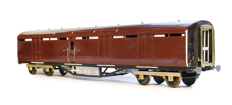
The picture features a Gresley BG but having done a little research it appears that the Hornby one, although nice on first inspection has some issues with the shape. So I went with an old Bachmann Thompson version instead. These also have issues with the shape as the roof had a bit of harsh angle on the sides but thats a relatively easy fix with a file. Underframe details are from MJT, bogies Brassmasters 8ft versions and the gangways are from Wizard models. The buffers are MJT as well being cut down 18 inch heads mounted on bit of tube to thicken up and lengthen the shanks. The cosmetic bogie sides (which I was waiting on when I took this image are again from MJT. The Bachmann ones seem a bit of a weird wheelbase for some reason.
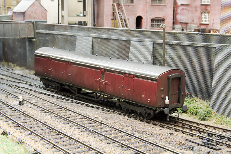 Another slight advantage of doing this coach is I can substitute it for a Midland BG on my milk train and make it a little more eastern region for when I get to play with North Elmham.
  Eagle eyed readers might spot the screw coupling on the one end. These coaches didn’t have them but anyone who has tried to couple a loco coupling to a coach with gangways at an exhibition will tell you that it’s nigh on impossible so in this case it’s a necessary compromise.
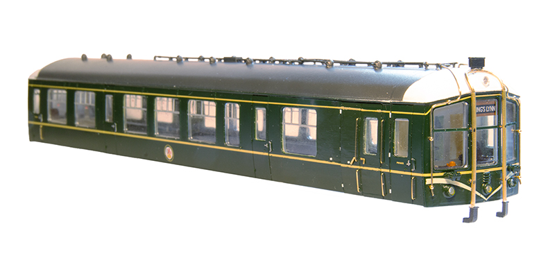 Speaking of North Elmham Tim mentioned that he liked the idea of a single car Derby lightweight. So given he knows I quite enjoy chopping DMUS about and having been suppled with a Bachmann 2 car set Ive come up with this. I wanted to avoid repainting it and found where i did need to revisit the green, Pheonix Precision BR logo green (post 1954) is an exact match.
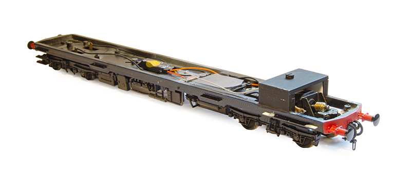 The Bachmann drive arrangement is pretty big and chunky on these. In a regular Derby lightweight you can sort of get away with it as it only really protruded as far as the last passenger door. On the single car with its extra window it would be way to obvious so a Hight Level Kits Lo-rider power bogie has been used instead. As North Elmham is set in the daytime Tim didn’t need the lighting so that was all removed.
 You can see from tis image why the original drive arrangement had to go. I used a slightly lighter underframe colour that usual as North Elmham isn’t set in the rain.
Forever Autumn
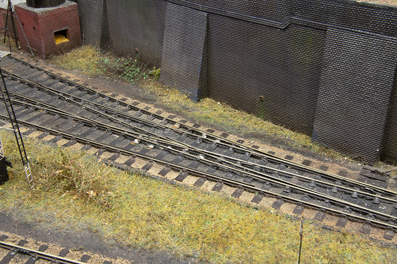
Wandering around at the back end of October last year I became aware that Brettell Road might not have enough fallen leaves to accurately represent the time of the year I was trying to depict. Theres 2 types of autumn. The really pretty one thats kind of fleeting and gets used in image libraries and on jigsaws. Then theres the drudgy one that doesn’t but hangs around a lot longer. You can probably guess which one of those two I decided I wanted.
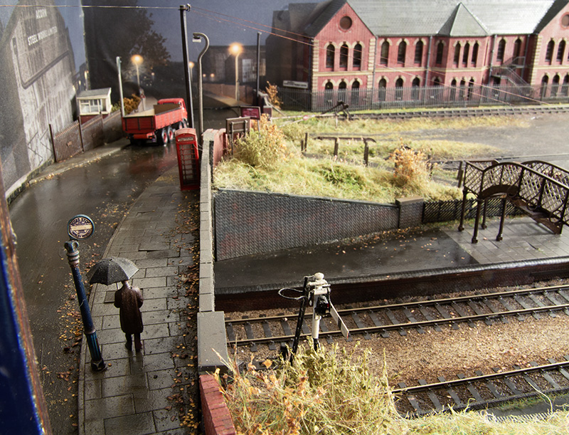
On the backscene on the end of the layout theres a line of trees that hints at the line continuing to curve to the right as you head towards Stourbridge. So these are the source for a spot of leaf litter. Ive always assumed that the wind is blowing from the left as you look at the layout and the weathering of the wet bits has always reflected this. To get the mulch I wanted I used a combination of kids power paint scatter and a couple of different types of autumnal leaves from AK Interactive mixed in place on the layout in a somewhat haphazard way and sealed with AK sand and gravel fixer. Once dry it was given another coat of wet effects fluid to blend it all together. I included a little more overflow down onto the platform and the tracks and I might revisit this and add more along the platform edge. Although the line speed on the layout is only 35mph and most trains entering the platform are going slower than that it’s still reasonable to assume trains will blow leaves from the other side of the bridge along with them.
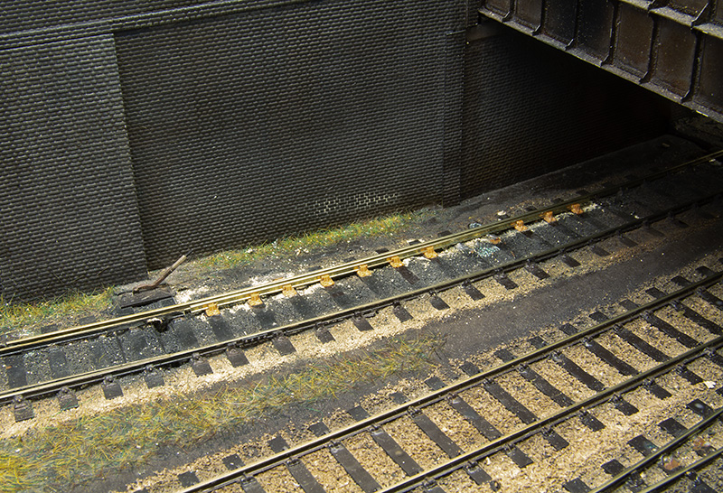
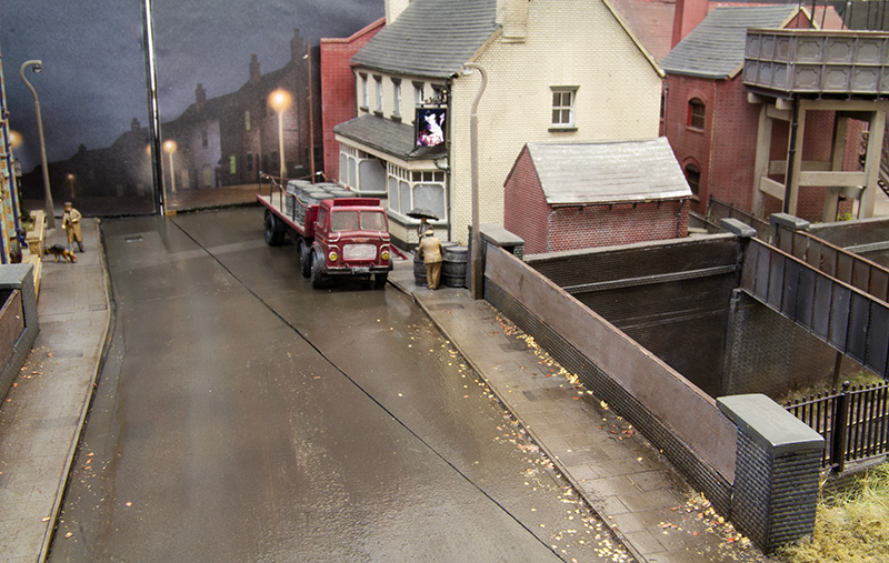 This is the central bridge and Ice assumed that there are more tress behind me. Again with a bias toward the leaves being blown from the left. Im not sure if they look a little bright here (no idea why as its the same technique using the same stuff) but next time I am weathering some underframes I might give a very light coat of dark mud to tone them down a little.
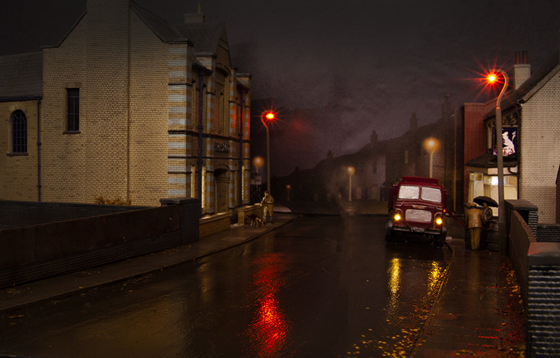 The same scene as above in a more intentional lighting.
![]() While I had the wet effects fluid out I gave the platforms another coat. Here we see the station in a quiet moment.
While I had the wet effects fluid out I gave the platforms another coat. Here we see the station in a quiet moment.
Variations on a theme – More vans
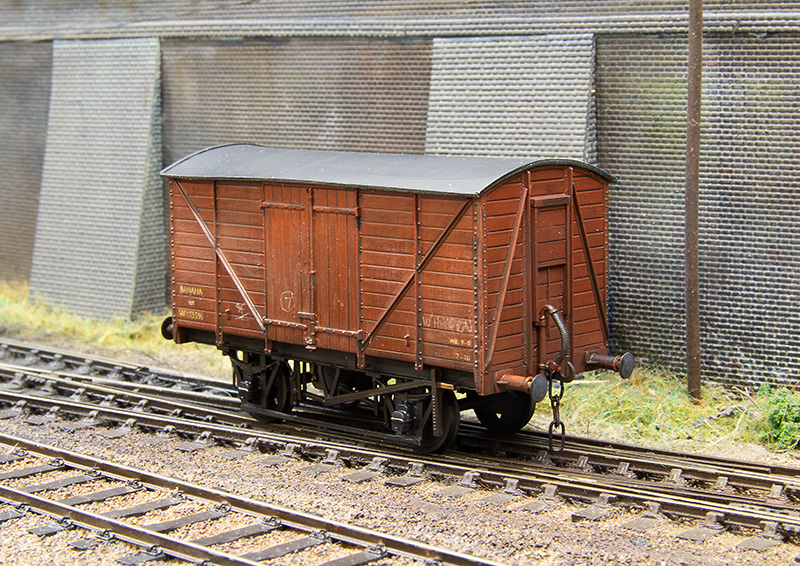
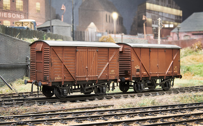 My somewhat hopeless addiction to building kits continues, I passed the point of having enough a long long time ago but there you go. This time all variations on types I’ve built before. Starting with the classic Airfix meat van. Or in this case just the ends of one and even then only part of the ends! Some meat vans lost their side vents and all but the top end vent. The Airfix ends are kinda chunky and can easily take having sections of them cut out and replaced with bits of plasticard. The rest of the van is all Parkside. Behind it is a standard Parkside plywood sided kit built as a fruit version.
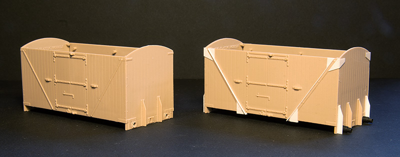
The Ratio Banana van kit. These are the second and third times I’ve built one of these and I’ve still yet to build one as the kit intended. On the left is the standard body and on the right modifications to convert it into the diagram 1/224 version.
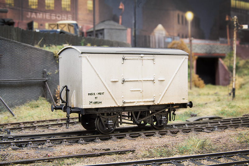 The first body was mated with a 9ft wheelbase chassis (stretched at the ends to fit) to produce a ex-LMS D1672 insulated meat van. By the time these were in BR service they lost the modifications that made them interresting. Those being roof mounted ice boxes and end ladders. Note the different wheels as per the prototype image in LMS wagons volume 1.
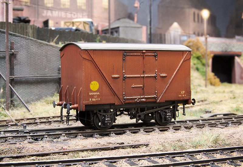 And the Diagram 1/224 version. Mounted on a detailed Red Panda chassis. Im just waiting for my friend to supply me some flexible steam heat hoses.
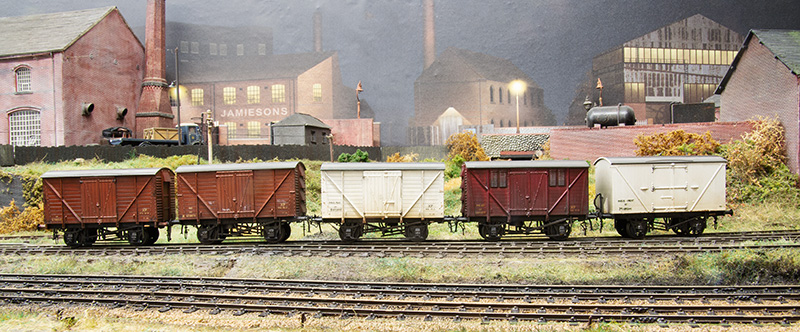
Some meat van variations – Left to right – the modified one shown at the start of the post. A similar one by the same method but with unmodified ends. A bog standard Parkside insulated one. The good old air-fix original (with Parkside doors and underframe) and the D1672 version.
And similar for Banana vans – Left to right D2111 LMS van from the Ratio kit on a shortened Parkside chassis. The Diagram 1/224 van. The ex GWR Y7 i featured last time and 2 Diagram 1/246 from the old Hornby Dublo bodies mounted on detailed Red Panda Chassis.
A few old kit builds
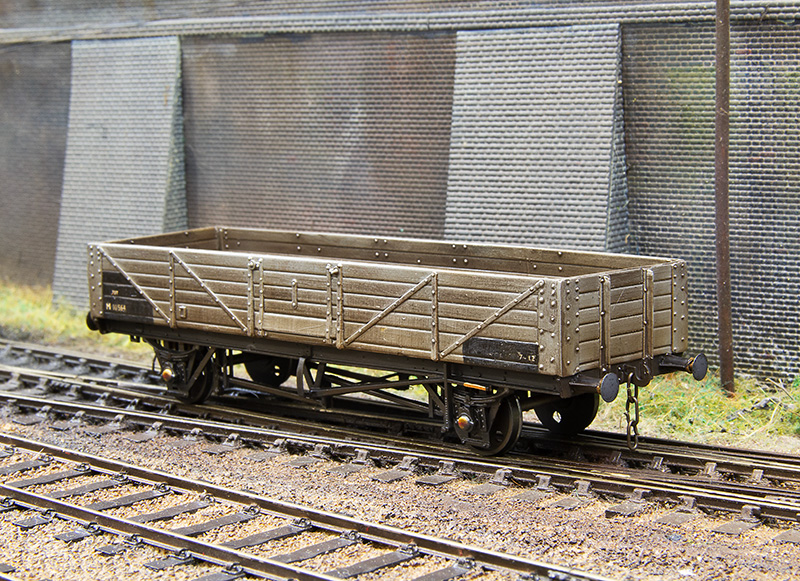
Been filling the odd moment here and there with some kit builds of fairly old vintage. The above is an LMS 22t tube from the old Ian Kirk kit. I replaced the bearings with MJT roller bearings based on a photo of a very similar wagon in Don Rowlands Twilight Of The Goods book. The hand brakes (which are too long in the kit as provided and are only one type) are spares from the Parkside 12ft chassis kit. 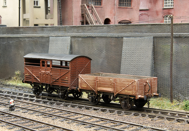
Digram 1/120 LNER open from the Parkside kit. Whilst this kit is still readily available it is one of their older toolings. I enjoyed doing the weathering on my china clay rake and have seen photos with similarly weathered opens in normal freight trains so I returned to that for this one. The cattle van is a diagram w5 from the Coopercraft kit. Both have had extra detail with the GWR brakes coming from Mainly Trains and Morgan Designs etched parts
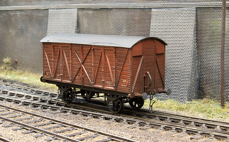 Next up another Ian Kirk kit, this time for the GWR mink C. I used the ends from the Ratio GWR 12t van kit, the ones in the kit had end vents and looked too narrow to me. I’ve added extra details to the body and underframe. Being on a 12ft wb underframe it’s something a little different.
Finally the left over sides from the above model were mated with Airfix cattle van ends to produce a Fruit B Diagram y7 banana van (I’m not sure that this designation is correct but it what the Didcot Railway Centre website refers to them as). The end vents were scratch-built and the underframe is a Parkside 9ft one with the ends stretched a bit.
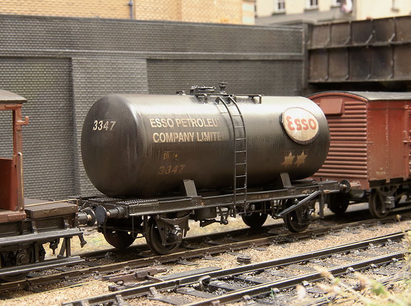
Not me
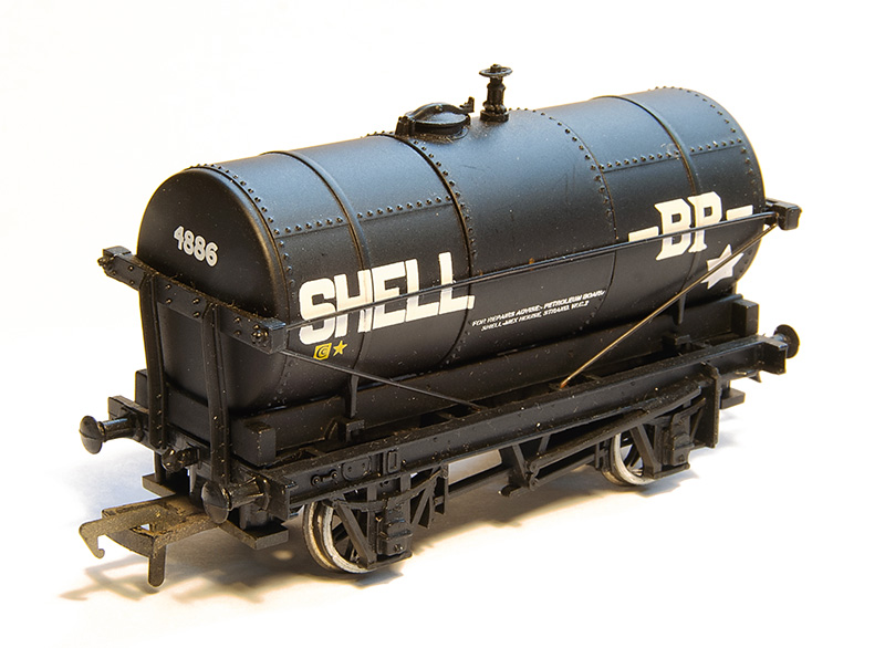
 Appearing at Scaleforum was this Hurst Nelson 14T chlorine tank, incredibly generously donated by Colin Craig. He was building a batch for Mostyn and added an earlier version for me. These would not have ventured to the Black Country but years ago I helped Dave Clarke, Along with Simon Stephens, take out his layout Amlwch to various shows around the country. Amlwch (pronounced Amlook) was the location of the Associated Octel plant and while the exchange sidings for it never featured on the layout and we never had the chemical tank trains its a nice little nod to a bit of my personal modelling history.
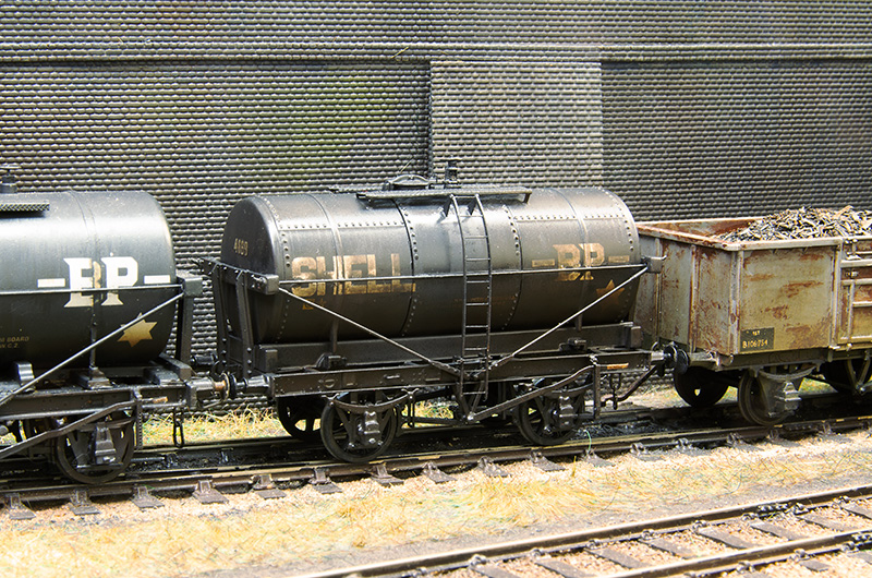
None of this wagon is any of my work. I did tweak the weathering a little from how Colin supplied it as the top of a white tank in the steam era wouldn’t be a clean as in Mostyn’s diesel era. I added the required wet look for Brettell road.
For more on Associated Octel click here.
 Next up another tank that I’ve not had a lot to do with really. The recently introduced demountable tank wagon RTR from Clarke Railworks. I rarely buy anything new RTR and this is the first brand new rail vehicle I’ve brought from any of the new generation manufacturers. In fact it’s the first new RTR thing I’ve brought since 2017 and the time before that was 2012 I think. I seriously doubt I’m paying any bonuses in RTR land at the moment.
So the wagon then, nice box and instruction booklet (looking at youtube reviewers these things seem important). The box will still look nice in my bin too! To be fair the instruction booklet is nicely laid out with clear illustrations of how to swap the wheels for em/P4. Which is dead easy, P4 wheels just drop in once the brake rigging has been unclipped and brass bearings are already installed. The brake shoes are kind of wide for 00 and a bit narrow for p4 but not enough to make you want to faff about moving them. The wagon weighs 30 grams out of the box which is lighter than my aimed for standard of 50g but some test shuffling around on Brettell Road didn’t show up any problems with this.
The couplings were replaced for Smiths and the (strangely) missing brake gear safety loops added. There a bit of a trench down the side of the tank and this was filled with Mr Surfacer 1000 liquid filler and gently sanded back. The colour was matched from a mix of blue and black. You don’t want to completely eradicate the line as it is visible on the real wagon. I think the branding should be parallel to the wagon and not the tank (which itself slopes at one end) but I might be wrong. Either way I left it as it was. The lamp irons were painted black (white lamp irons weren’t a thing yet) and that was about it, with the obligatory weathering of course.
Scaleforum 2025 ticked off

Well Scaleforum 2025 is ticked off as is my exhibition diary for this year. I’m happy to report that everything went very well and all that effort put into amending the cassettes post York was well and truly worth it. Theres a small list of things to fiddle with, there always is, and less than an handful of errant wagons are waiting to be spoken to. We all enjoyed ourselves and I’d like to extend my thanks to the Scalefour society and everyone who took the time to stop by. Many kind words were humbly received.
 It’s changed a bit since the first Scaleforum we did back in 2017. Next up is Macclesfield in April 2026.
A bit of Deja-vu
Ive been wagon building again but but its all stuff I’ve done before (well sort of)

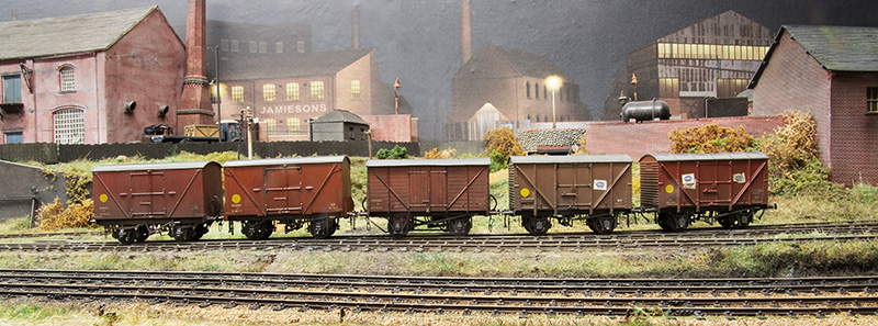
Starting with this little selection of fairly mundane vans (with a cheeky Airfix mineral tacked on the end). The nearest van is a Southern diagram 1452 plywood van from the Ratio kit. I used a parkside underframe and reprofiled the roof as the moulding flared out too much at the bottom. The repair patches are a neat little etch from RT models. The next one along is a bog standard Br 12 tonner from the Parkside kit and the cattle van is Airfix. You can see what i did to an earlier one by clicking here.

Next up an ex GWR Y8 fruit van. This uses Bachmann RTR sides and Parkside ends as the RTR body is too wide. Steve Carter has already written about this conversion on Kier Hardy’s site so there’s no real point in repeating whats already put there. Heres a link scroll to about halfway down. Just a quick note of thanks to Richard Oldfield for assisting with locating some buffers. On the 3 10ft wheelbase vans I’ve deviated from my normal approach of building them rigid by using the Dave Bradwell spring plates. Just as a bit of an experiment. See here – about halfway down

Ive been here before too – LMS D1994 milk tank from mostly Rumney models etches with a Lima Tank. My original one is the one on the right. As a slight variation the one I’ve just done uses the earlier style of underframe. (see here for the original build)
 And D2173. These had sloping tanks and discharge at only one end. Justin kindly supplied me a test etch for the platform.
 My little milk train in its entirety.
Project 2f part 2
 Concluding my 2F project by starting with the tender The coal rails were from the kit as was the tool box.

Lamp irons from Stenson Models – Vac pipe from Lanarkshire Models. 
On the inside I made a representation of the coal space from thin plasticard – I wasn’t too fussed about blending this into the existing space as it will be covered in coal.

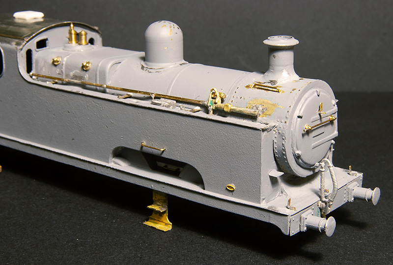
On to the loco then, with details fitted.

The washout plugs are kind of loco specific so as always – check your prototype. Also check the date. I found another picture of 58185 at Harbourne, so the same loco, at the same place, even under the same bridge, but as it was a little later the smokebox door was different. Alan Gibson do some nice lost wax washout plugs (I used them on my flatiron) but he hadn’t got any so i knocked some up from bits of brass.
 The kit includes a casting for the injectors but its the later combined type. I previously made the version I needed for my 2441 tank from bits of wire and tube so I just copied what i did last time.
 Some rudimentary cab details – I tend not to go too mad on this stuff as there will be a crew in the way. The floor is a bit of lead as any weight helps. The inside of the firebox is also lined with lead.

Inside motion modified from the Brassmasters etch. (This is the fifth time I’ve done this now – does it count as an addiction at this point I wonder?) I soldered some small tubes of brass on the chassis side face of the CSB springing plates to give me as much room as i could otherwise the tabs would have been in the way.

Next stage – – couple of light coats of etching primer. Check for any gaps or rough bits and add any needed rivets -Luckily theres not a lot of them on this class of loco. 
The end result.


These locos really are diminutive – pictured here alongside a 3f
 A comparison of the 2 tender sizes.
 Not by any kind of deliberate design I have ended up with quite a little family of Johnson designs now.

Project 2F
 Those who kindly stopped by for a chat at Scalefour Crewe will have seen me fiddling with a set of loco frames. Above is the progress I made over 2 days which to be honest isn’t a lot but that’s a good thing. I always feel that if you get a decent amount of stuff done demoing at a show you’ve kind of missed the point of why you were there!
The Johnson 2f minefield.
The frames are an old Alan Gibson kit for the Johnson 2f or 1142 class, sometimes referred to as ‘mineral engines’. These and the similar 1357 class are often lumped together as 2Fs but there are a whole ton of differences between locos regardless of the actual class. I recommend a couple of books if you want to go into a lot of detail These being Stephen Summerson’s ‘Midland Railway Locomotives’ Volume 4 and Bob Essery and David Jenkinson’s ‘An Illustrated History of LMS locomotives’ volume 4.
The 1142 class 2fs were built by 4 builders over a 2 year period. Those being Kitson, Dubs, Beyer Peacock and finally Neilson. Initially they were very handsome locos and had a family resemblance with the 700 class Kirtley goods, if you put the laters outside frames to one side. As with all things Midland they were modified over their lives with Belpaire fireboxes and 2 different types of Deeley cab. The lower roof one being the better proportioned of the 2. The class had so many modifications that it’s definitely a case of pick a prototype and model what you see. Some had sandboxes at the outer end of the frames. Some either side of the middle driving wheels. Chimneys were all sorts of different heights too. The main oft’ quoted difference between the 1142 and 1357 classes is the wheel size. the former having 4ft 10in drivers and the latter 5ft 3in. An easy way to tell them apart is the 1142’s had brake linkages outside of the wheels while the 1357’s had them inside. Well most of them did anyway but there are some exceptions to that as well.

 So my intended victim. Pictured here at Harbourne station in 1957. Ive long like the first image due to its run down nature. The station having been closed to passengers in 1934. At the time the picture was taken it was beign used as a wood store for the nearby Chad Valley toy factory. Note also the LMS open stil with its LMS lettering. Both images © 2015 – 53A Models of Hull Collection and used with kind permission.
58185 was one of the Neilson builds being constructed in 1876 and lasting until 1962 (86 years!). It was originally numbered 1245, then 3013 followed by 23014 before receiving the BR number in 1948.
The Kit
It would be fair to say the Alan Gibson kit is of its time and was probably towards the higher end of kit design when it was released. It doesn’t have any of the slot and tab style niceties we are accustomed to these days though. You can see from the top picture that I used some Alan Gibson frame spacers and drilled the frames for CSB suspension using the info on the CLAG site as a guide (see here)  Progress so far handrails and details next. I found using a High Level Kits road runner plus gearbox with their D1 drive stretcher and a smallish motor I can get the gearbox into the boiler without having to cut into the boiler itself (which was just a bit of brass tube). It’s worth noting that if you want to do the original version London Road models do a kit for it.
The Johnson tender
Yes another minefield. These come in a multitude of different sizes. those being 2,350 gallons, 2750, 2950, 3250 and 3500 gallons. Some of the early ones came with springs above or below the footplate and there were were different inner face designs too. My kit came with the 2,350 gallon version but my prototype has the 2,950 gallon version. As the kit as clearly too small a Bachman spare body for the 3,250 gallon one was brought from their spares site. Im far from put off by a bit of plastic bashing.
The Bachmann model is pretty accurate for what it represents. A comparison of the key tank dimensions are (Bachmann/3,250) length – 77mm, width – 28.3mm, height – 16mm. The 2,950 gallon tank is length – 76.3mm, width – 26.1mm, height – 15.6mm. So that differences of 0.7mm, 2.2mm and 0.4mm respectively. I often think it’s a good exercise to think of these number in 2 ways – percentages and relationships. Dealing with percentages first the differences are 0.9%in the length, 8% in the width and 2 and a half% in the height. Its fair to say that the difference in length is all but impossible to see. The height probably not but the width is probably pretty noticeable. That brings me on to relationships. The tender and cab width are the same. If the tender was over a mm wider each side that would definitely look odd. The height as a number is harder to tell but the bottom of the beading lines up with the top of the cabside beading and this relationship is kinda obvious. Some of the class had the larger 3,250 gallon tender and this height is pretty obvious once you are aware of it.
Modellers licence
Some quick measurements showed that dropping the height of the tender by half a mm wouldn’t give the relationship to the cab I was after so I reduced the heigh by 1mm. Yes it means the tender is now a bit too low but the relationship to the cab is better.

The Bachmann tender cut into manageable chunks. The new lower beading is 10×60 though evergreen strip.
 A rough mock up. The inner chassis is Brassmasters from their 3f easychas and the outer frames, brakes and springs are from the Gibson kit. The bufferbeams are also Brassmasters and the buffers are from Lanarkshire models.

Progress so far.
Post York show Part 2
Continuing from the last post. I mentioned a revision to the lead in from the cassettes to the layout. Below is a quick video of a bit of a drastic test.
In reality no trains will inter the layout at this speed and aside from the industrial entrance behind the warehouse none of them will be pushed.
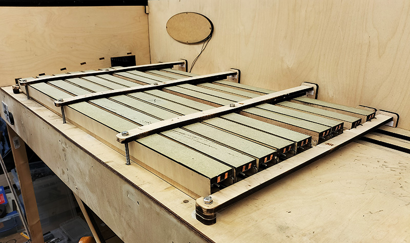 The cassettes are finally done. This is the long ones in their storage position in the station end fiddleyard.
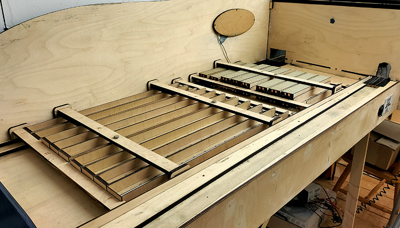 And the DMU and loco ones in the Dudley end fiddleyard. Im not usually one for counting parts but including the 5 connectors on the layout thats a total of 86 ends, 172 springs and just over 6 meters of copper strip. Ive had better projects to do before now!
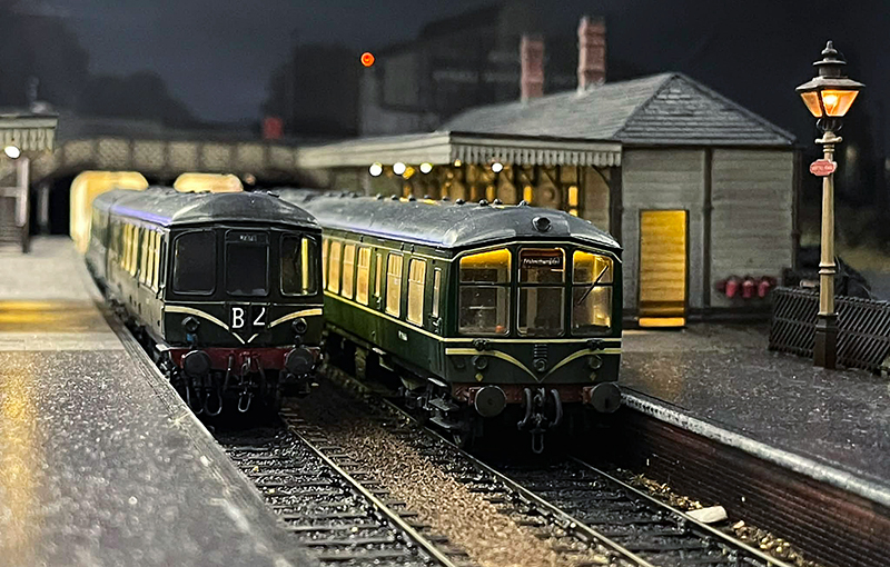
 On to the tweaks on the layout itself. Just a few of these. Those at the show may have seen the odd derailment of stuff coming into the Stourbridge platform. The Derby lightweight seeming particularly susceptible to this. Turns out the barrow crossing on the left hand rail has become loose and was higher than the rail head. The crossing on the Dudley line was also a tad high but not loose so I’ve removed both to get a better fit. The Derby lightweight will be checked too to see if theres any problems on the stock side.
 I noticed when cleaning the track that one of the smaller sections of track on the threeway was a little low. I don’t recall anything coming off on this particular bit but I’ve fixed it anyway. There were a few tight spots that have been amended too. My mint block would go through but with a bit more resistance than I liked. One of the tight spots was between the running rail and the check rail. Just need to put new half chairs in place and cosmetic fishplates. Then paint the rail and blend it all back in.
 Finally the check rail coming in to the yard was originally an after thought on normal flexi-track. It wasn’t as neat as it could have been and being normal track there was no gauge widening on what it the tightest curve on the layout. The far rail was removed with the moulded chairs smoothed away and the rail replaced with proper check rail chairs.
York show post-mortem
Over the Easter weekend Brettel Road headed north 3 hours to the York MRC exhibition. 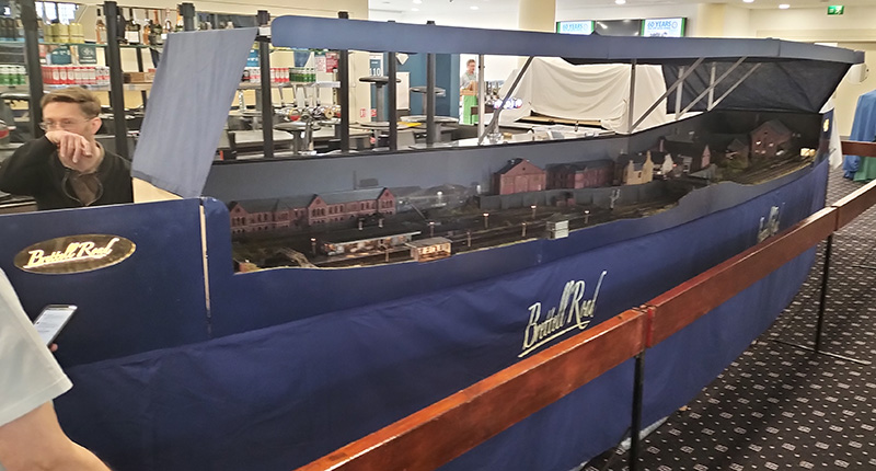
Despite a minor cardiac event at 5pm on the Thursday evening when it looked like the van may not be available due to a medical emergency set up went smoothly. Little did I know what was to come over the next 3 days.
We had problems! The biggie was that the cassettes were still not reliable, to the point where they were the worst they have ever been. Despite this the guys battled on against the layout that was absolutely determined to fight us ever step of the way (thanks again chaps). There was a problem with the main point into the yard behind the station which I did manage to patch up on the Saturday afternoon and the track in the yard under the bridge (of course it was!) had become damaged. Something we didn’t notice until a member of the public kindly let us know. The whole show was a mixture of frustration and some degree of embarrassment really that the layout was performing as smoothly as the proverbial bag of nails. Despite all this we did still attract a lot of interest throughout the 3 days and many kind compliments were received along with 4 or possibly 5 requests to take it out to more shows so I guess from the public side of the barrier it didn’t seem quite as disastrous as it did to me. Thanks to the guys at York MRC for having us and looking after us so well. The elements of the weekend that didn’t involve the layout were great!
Diagnosing the problem
The problem with the cassettes was two fold and wasn’t something we could really address at the show. Brettell Road actually has 45 cassettes in total in 3 different sizes.
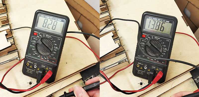 When I built and tested them originally, I tested them for resistance using the buzzer in my volt meter. What I didn’t test was if there was any voltage drop or not. On the left are 3 loco cassettes of the design we had at York showing a voltage drop of over 5 and a half volts or as good as 40%! Little wonder it caused us grief. On the right a revised design tested on 3 cassettes with no loss of volts at all.
 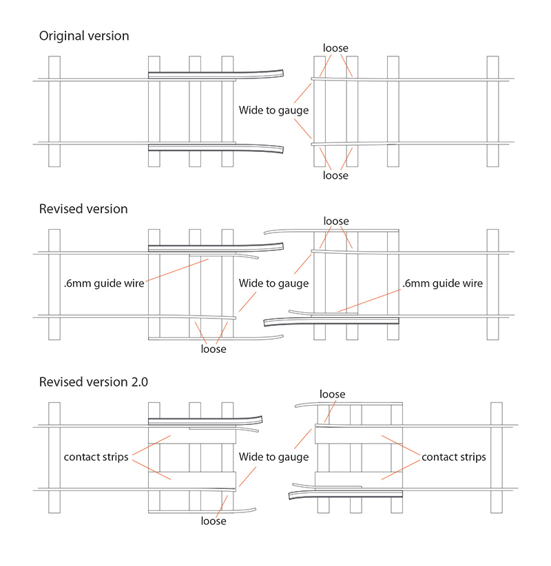 A little diagram of my cassette evolution. The top design is what I used on the short version of the layout and that seemed to work fine. As these cassettes were single ended I also fitted a light to them so that we could see that they were electrically connected.
With version 2 I wanted them to be double ended and introduced the idea of smaller loco cassettes. This had 2 effects. While on version 1 the rails were squeezed tightly by the guide rails on the revised version the fit was less positive. The second effect is a loco cassette doubles the number of connections. If everything is really clean they work just fine however in the real word things don’t stay really clean for long. Because of the design, the bits I needed to keep clean were hard to get to and the sort of area what would naturally collect dirt and crud. The loose stock rails were also still prone to go the wrong side of the guide wire and I found many had failed at the soldered joint on the third sleeper in exaggerating the problem. I guess my absolute minimal solder approach I use when building kits isn’t such a good idea in this application.
The solution is to add contact strips from 0.2mm thick, 5mm wide copper that fold down the front giving a much bigger contact area that, just as importantly is easier to get to to keep clean. I also reduced the length of the rails that stick out and soldered the loose rail to an extra sleeper so it doesn’t move as much. The cassettes are kept in compression when on the layout by a simple peg (actually cheap, small screwdrivers) fitted into holes drilled into the baseboards.
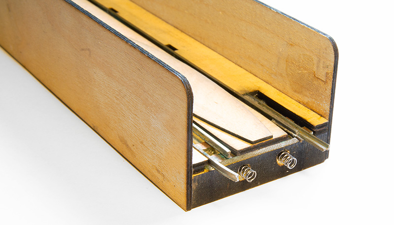 Now this is a bit belt and braces but on an exhibition layout thats never a bad thing. Rather than just rely on the springiness of the copper strips I drilled holes behind them and fitted a couple of spring (actually springs from smiths coupling hooks that id been saving for some unknown reason).
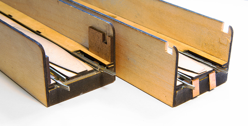
Before and after. The little side parts that hole the cassette ‘buffer stops’ were still causing problems so I’ve decided to remove them completely and redesign the stops.
 I also took the opportunity to move the cassettes back a little and extend the lead in roads as we were having derailments coming onto the layout at both ends. This may have been the cassettes or it may have been something else. Originally I had check rails here but tests of the new sections without them is making me think they were unnecessary.
Pre-show tweaks.
Been doing some final pre show tweaks before Brettell Road heads off to York in a little over a week. 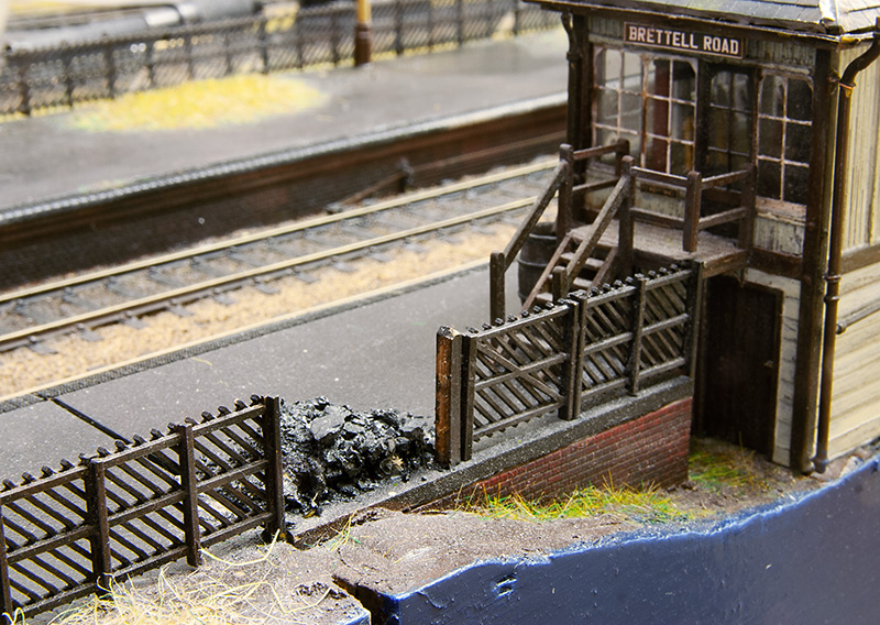
After the last show (nearly a year ago now) there was a little bit of damage picked up. Nothing too major and the kind of job that I intend to get around to at some point but then don’t. Case in point this but of fence which got squished. 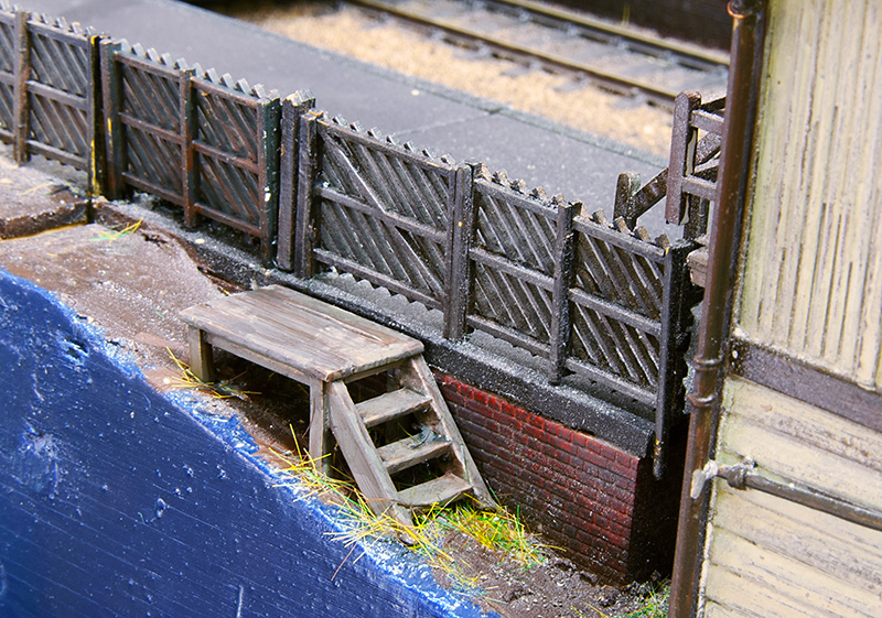 While working on this area I took the opportunity to add some rudimentary steps to the signal box. Something I meant to do at the start but didn’t. I had put the gate in but the poor signaller would break his leg falling off the edge of the platform! There was also a platform light that got bent and thats been repaired and replanted.
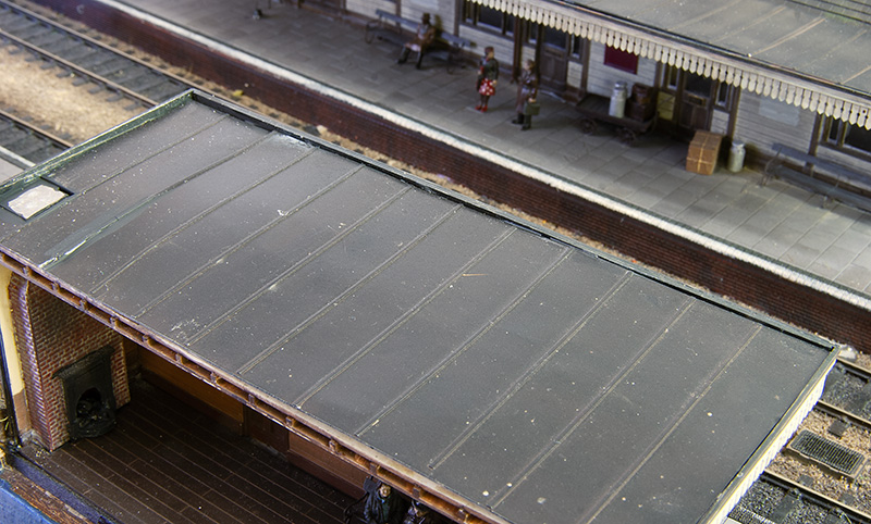 Something else that got bashed but didn’t actually break is the chimney on the platform shelter. This has very little clearance to the other board when packed up so rather than wait for it to get smushed I decided to make it removable. A few magnets popped into holes and a bit of steel on the roof and hopefully thats a problem averted. I also decided that the roof was a bit too vanilla for a building due to be closed in a week so I’ve had a look at this area too.
 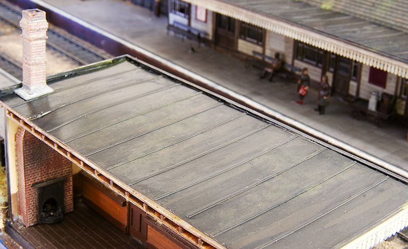 You may remember i talked about distress paint before when I was building the signal box and I’ve used it again here. For some reason it didn’t really crinkle up this time so a wash of Tamiya extra thin cement was painted on to add some more wear and tear. The mossy deposits are AK Interactive dark and light slime with some of their moss deposits.
Next is track cleaning and hoovering before packing the boards away, then the joy that is cleaning wheels!
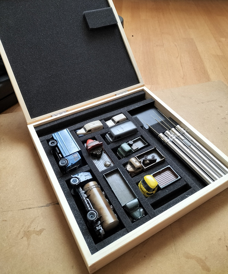 In an uncharacteristic fit of tidiness I’ve made a proper box for the road vehicles, removable chimneys and coupling poles. When I say ‘made’ I mean got a box off ebay for around a tenner and stuck some foam in it!
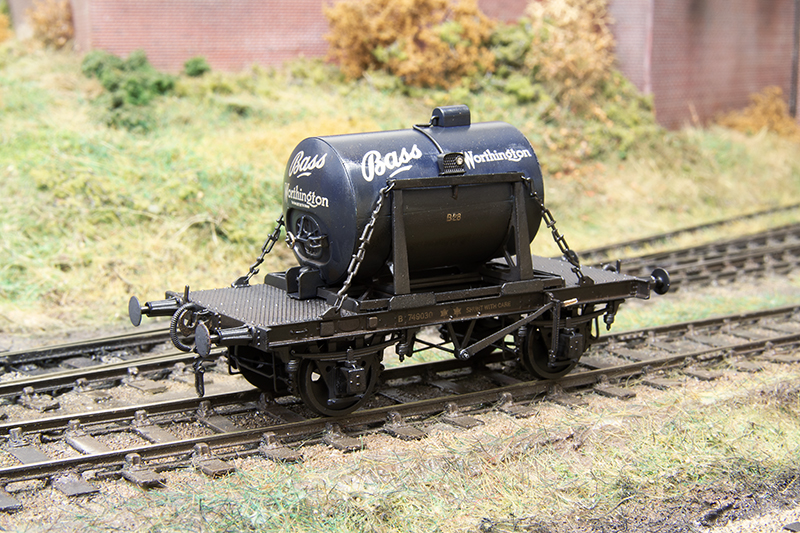
The saddle mounted tank I featured last time is done and tested. 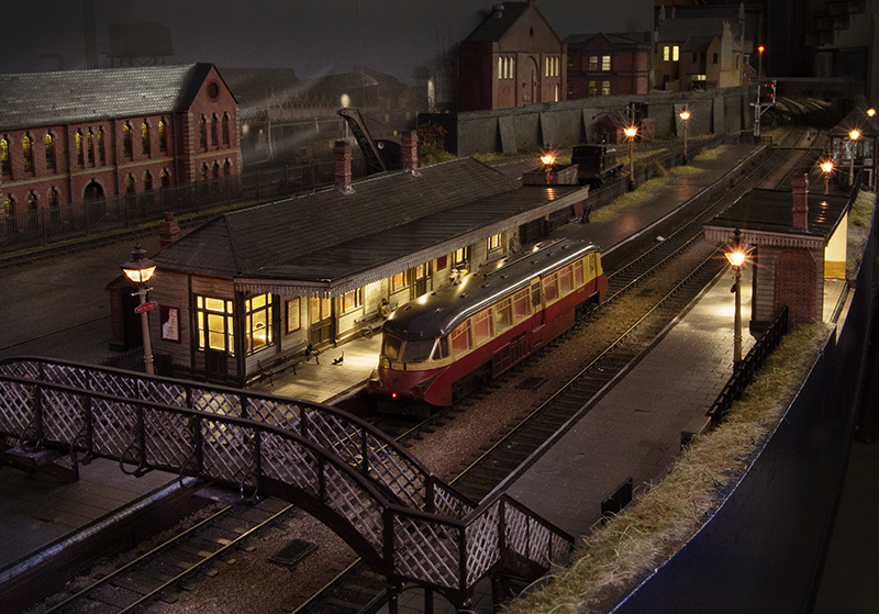 Finally Railcar W14 waits for the road. The cats are undisturbed by its presence.
Info on the York show. Please say hi if you are going.
A trio of tanks.
A trio of tanks this time starting with…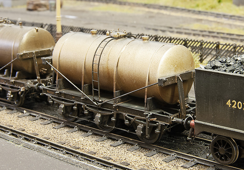 … the LMS milk tank I featured last time. Now ready for service.
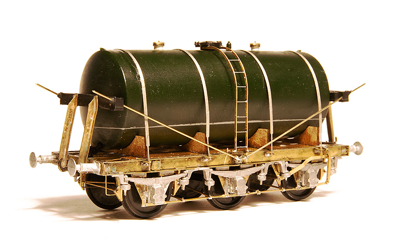
The Bachmann 14t cradle mounted tank wagon. Very much of its time with a very generic (and pretty rubbish if I’m honest) chassis. 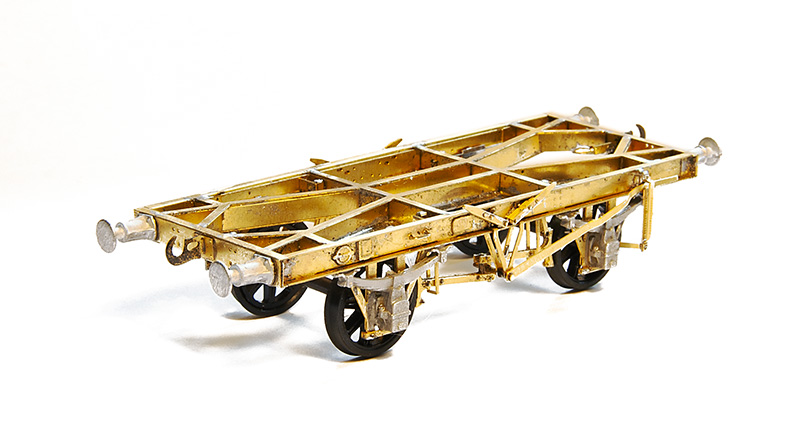
Luckily Justin does something a little more refined and very nice to build it is too.
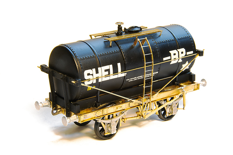
Ready for the brass bits to be painted. The ladder is only loosely in place. The walkway is from my box of useful stuff (I think Stenson models) and the buffers are from Lanarkshire Models.
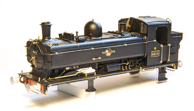
Still sticking with the theme of tanks but is a slightly dubious way, work in progress on a 96xx tank. I originally picked this up quite cheaply with and idea to include it in my scrap train. Round Oak scrapped quite a few locos, but it didn’t take me long to decide to do it as a working loco instead. Especially as a picture of this very loco heading a freight train through Brettell Lane cropped up in my facebook feed.
As far as I can tell this model by Bachmann is an evolution of the Mainline model I’ve already used to do my 57xx tank, with a later cab and other refinements. All of the handrails are separately fitted but I felt the handrail knobs were way too big so I replaced them with Alan Gibson ones. I reused the long handrail but as its not so wide i had to cut it in half to lose a little from the middle. The sandbox fillers are too far forward as they were repositioned with RT Models linkages but not before the front splasher was cut down in height. A compromise for the over sized flanges on the RTR wheels and something that has entered my ‘now I’ve seen it, i cant unsee it’ mindset when looking at model steam locos. Smoke box dart is also Gibson and the lamp irons are from Masokits. I also replaced the pipes on the footplate. Some 96xx had a bracket half way along with i quite liked but unfortunately 9614 was one that didn’t.
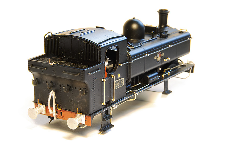 Rear view. The lamp irons were too high up on the bunker. This is correct for a 57xx but on the 96xx tanks they were lower. I was replacing them anyway. Buffers are Lanarkshire models. I prefer a better detailed solid buffer over a less detailed sprung one.
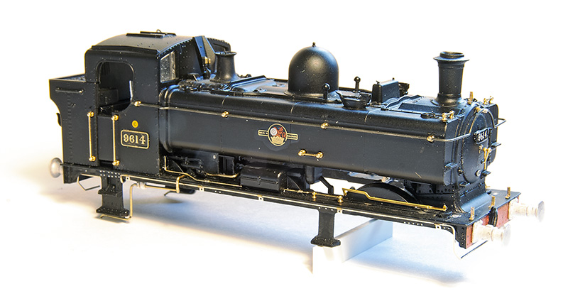
Drivers side. The pipework just in front of the cab is the same on both sides of the model. Again OK for a 57xx but on the 96xx they were different with a somewhat more barren look on this side. The footplate pipework is also routed differently around the cab footsteps. Chassis will be a high level one with my working inside motion bodge as described here. https://p4newstreet.com/an-unremarkable-little-tank-engine-part-1/
 Finally something that you will never see – Brettell road in the sun! It was coming in the shed door and caught my attention.
return to milk tanks
My history with milk tanks has been, to an extent unnecessarily convoluted. Originally I planned to build a David Geen kit for a midland one and I got the Rumney Models underframe for it in preparation. However when I came to get the kit from David he only had one left and that was for a GWR one. Justin kindly swapped the chassis kit for me and, as I’ve mentioned before, doing battle with my collection of bits I ended up with my model of a milk tank.
However the desire for at least one LMS one never went away and for more years than it really should have been I would discuss the idea of doing one using Rumney bits with a Lima tank when I saw Justin at a show. Apparently I wasn’t the only one
Well finally, heres what I’ve come up with, The only bits of the Lima one left are the tank – end supports and filler hatch. The rest is pretty much all Justin with buffers from Lanarkshire models and the tank supports kindly cut for me by Tim Horn.
The diagonal bracing is obviously over-length at the moment. The strapping isn’t tight and the ladder is just rested in position until after painting. This seemed much less of a fight than my other one, so much so that I’ve ordered bits to do another 2.
A batch of good old Airfix kits
I recently picked up a batch of good old Airfix wagon kits. There were 4 brake vans, a 35t tank, a 16t mineral wagon and a cattle van. Of those one of the brake vans was finished and another one along with the 16t mineral were semi completed. I really wanted the brake vans as I had identified a need for more BR ones and more that were fitted as up until now I didn’t have any at all, just a couple of piped ones.
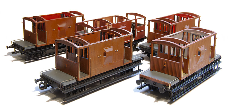 Note to self – if you’re going to batch build some wagons don’t pick ones that have loads of different sized handrails!
 The first 2. A piped one and a fitted one, both built with Bill Bedford W irons, Rumney models springs and axleboxes and additional details.
 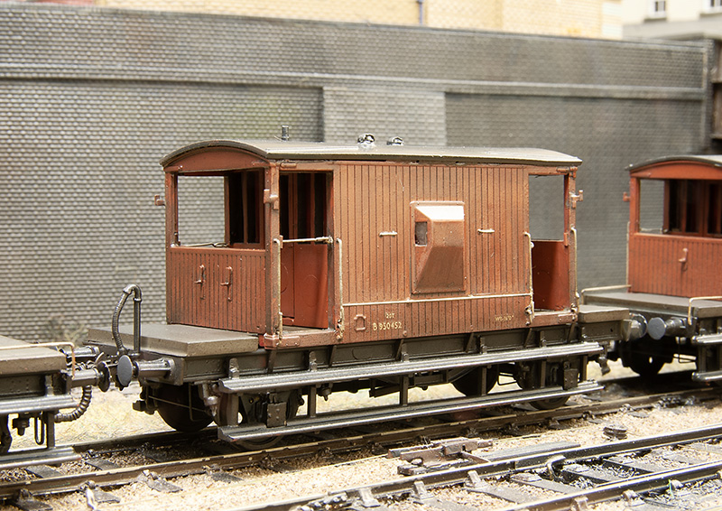 This one is a BR build of the LNER design note the shorter steps, no end handrails and different lamp irons. Build was the same as the first 2.
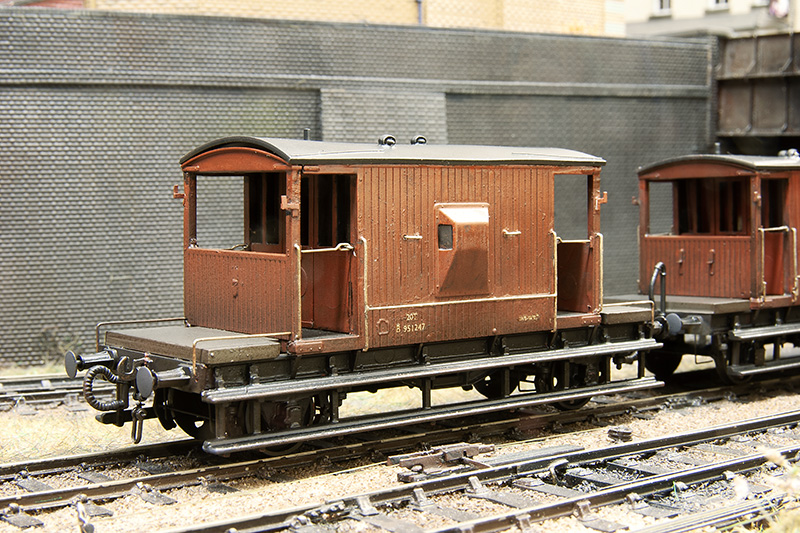
This was the last one and the one that was already built. I replaced the handrails and roof and added the same details as the other 3. This one is unsprung.
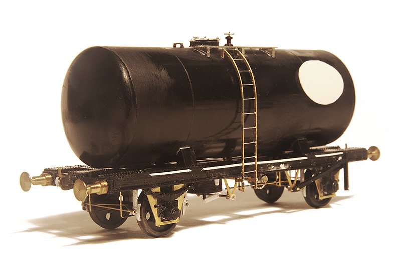
On to the tank wagon. Not one this done before. This is sprung with Bill Bedford W irons. As supplied the solebars are too shallow so I carefully cut the top rib off flush with the face and added a new top rib from microstrip. Buffers are from my draw of buffers and I think they may be from A1 models. RT models do a nice little etch for these and while the ladder supplied is really nicely done it is a flat etch so I replaced them with ones from Rumney models. I replaced the brake gear with bits from the spares box.
The finished wagon. Transfers are from Cambridge Custom Transfers.
Flights of Fancy – Part 2
 I ended the first part of this project by mentioning I needed some bits from Scaleforum. One of these was the injector which I modified a little from an Alan Gibson one.
 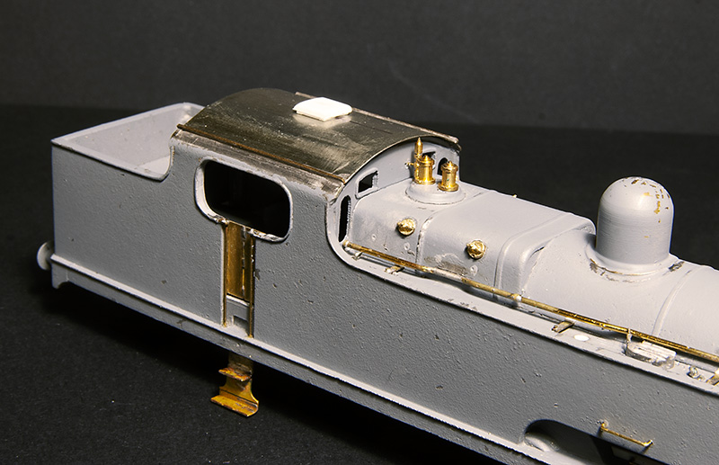 I also needed some firebox wash out plugs. Again Alan Gibson did the honours. It’s worth noting that they are not on the same places either side. The cab roof was just a bit of nickel silver rolled to the right radius and a few bits of strip for the rainstrips. The vent was filed up from Evergreen section. While on the subject of the cab the kit includes some bits and an etched floor. I found the handbrake column, if mounted to the cab floor as the kit was designed, gets in the way when trying to mate the body and chassis together so I cut it from the floor and mounted it to the body instead. The kit specifies that the reversing screw is mounted on the left side of the cab but, while hard to see in photos, it seems to be mounted to the right side so thats what I did.
 With everything in place and being happy wit the fit of things the body was given another light undercoat before the missing rivets were added from my dwindling supply of Archers along with some from Railtec. Thankfully the flatirons dot have a lot of visible rivets.
 I don’t normally take a painted but pre-weathered picture but this time I made an exception. I mentioned in the last post that because of the carzatti front axle the coupling rods seemed backwards to the norm with the joint ahead of the middle axle not behind it. When No.2000 was modified this remained the case. The kit has the coupling rods the normal way round with the joint behind the middle axle and I’ve never seen a model flatiron (in either 4mm scale of 7mm scale) that addresses this. I found 52f models do a set that have the right wheelbase with the joint in the right place so I used those instead. One little tip that seems really obvious but I’ve never seen anyone mention (perhaps its because it is obvious to everyone else?) is that I line up the coupling rod on this side with the orientation of the grub screw on the final drive gear. It makes accessing the grub screw simple should you need to in the future as you know where to stop the wheels rotation.
Below some pictures of the finished loco with my usual caveat of still needing coal and a crew. 
 With her baby sister!
Flights of Fancy – Part 1

Long time readers may remember this illustration I did a fair few years ago. At the time I was toying with the idea of BR Flatiron for Brettell Road. People who know anything about these locos will know that they only made it as far as 1938 before the lastof them went for scrap but my theory was what if they didn’t and made it another 2o years or so? After all we are all happy to bend the historical truth when it comes to places but why not locos too?
A brief history
Samuel Johnson of the Midland Railway had identified a need for a large passenger tank engine in 1903 and while a 0-6-4 seemed a logical progression of their 0-4-4 tanks several ideas and arrangements were put forward both before and after the design by Deeley was settled on. These ranged from a 4-4-4, a 2-6-2 with odd split side tanks, through several variations of outside cylindered 2-6-4’s and a 4-6-4. All of the class of 40 were built in 1907. As it turned out this was not a wheel arrangement that would become at all common in the UK. The front axle was mounted into a Carzatti slide giving extra play and resulting in a somewhat backwards arrangement of coupling rod with the knuckle joint ahead of the middle axle and not behind it as was the norm.
In early LMS days the class were fitted wit new superheated Belpair boilers resulting in a different firebox and being longer, the boiler now sticking out from the front of the tanks. The cab spectacle plates were also changed at the same time.
In 1928 loco No.2015 derailed at speed near Newark and a passenger on its train was killed. 2 more derailments occurred in early 1935. The first instance was when N0.2023 derailed at Ashton under Hill in February, killing its driver. 3 weeks later number 2011 was observed by railway inspectors operating between Leicester and Burton upon Trent only to itself derail 5 days later at Moira. Fortunately this time no serious injuries occurred. But the reputation had set in, the class were well known as rough riders on anything other than perfect track and were noted to run smoother going backwards.
An idea not completely without precedent.
The case for these locos lasting longer than they did is not without precedent. Class leader N0.2000 underwent some modifications to see if the riding could be improved. These were the replacement of the front axle arrangement with traditional springs (giving a different look) and an improved bogie with side bolsters. No 2000 was tested against an unmodified classmate No.2012 which itself had recent general repairs and not yet clocked up 1000 miles since. Both locos were considered to be in first class running order.
On the first test No.2000 ran between 35 and 50 mph before selling back to 35 and it was reported that the engine rode very steadily with no side movement reported of the trailing bogie. Test 2 saw No.2000 run between 45 and 50mph settling back to 45 with the same results. Test 3 was run at 55 and occasionally 60mph and this test was satisfactory enough to try test 4 where she was run over 60mph, reaching a speed of 67 before selling back to 65. It was reported that a slight amount of side oscillation developed and a slight roll but was still considered satisfactory riding.
No.2012 ran 3 tests. Test 1, 35mph occasionally touching 40 and the riding was reported as good with a slight oscillation and roll being perceptible on the footplate. Test 2 saw 45mph with occasional 47 and the riding was considered fairly good but with more oscillation and tendency to roll. The final test saw running at 55mph with occasional 60 and the riding was reported as rough with the oscillation and roll said to be pronounced and the front end having a tendency to develop an up and down surging motion.
Although the results of the modifications to No.2000 were good Stanier decided that the rest of the class were not worth altering and between 1935 and 1938 they were all scrapped with many of the (standard) parts going on to other locos. It was reported that many of the boilers were used on 4f’s.
But what if Sanier thought the modification were worth doing to the entire class? They were only 30 years old and many midland locos lasted much longer than that. As the boilers went to other locos they were obviously good so it it such a leap to think that a modified flatiron could indeed make it into BR days with only a slight tweak of history is it?
The Model
Luckily for us South Eastern Finecast do a kit for these loco’s and I’ve had one in the stash pretty much since I did the drawing above.
Starting with the bogie as supplied on the left and my modified version on the right. It’s been modified mechanically to provide basic springing on all 4 wheels and a basic form of sprung side control. As supplied the bogie is designed to be attached to a swinging arm much like the RTR guys tend to do. I didn’t really like that idea much if I’m honest.
 The main frames modified with some spare Brassmasters inside motion bits. I considered there was no way you would be able to see working inside motion so just modelled the bits I felt you might see if you looked hard enough!
The cab Spectacle plate is a particularity weak point of the kit as it bears only a passing resemblance to the real thing, I made a new one from plasticard as can be seen on the right. If anyone wants the drawing for this (which I admit is a best guess on my part) it can be downloaded from here. The rebuilt cabs also seemed to have slightly longer roofs than the originals and little bits of Nickel strip were soldered to the corners to replicate this. 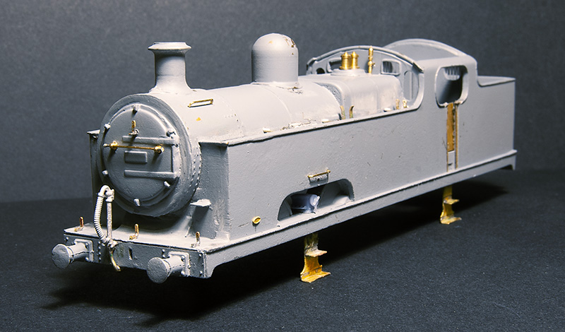 Front view. The kit relied on an upper half of the boiler/smokebox merging with the lower half which is cast as part of the tank front and this forming the front of the smokebox. The end result wasn’t all that round so I cut it back and used a 22mm copper ring in its place Buffers are from Lanarkshire Models and lamp irons from Stenson Models
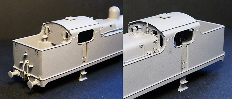
 The rear view. The steps are cast into the rear of the bunker and where a little chunky. Also the top one was too low so these were replaced with some of my mk1 coach end steps. The window frames are from a Mainly Trains spectacle plate etch. Note the larger buffers on this end.
 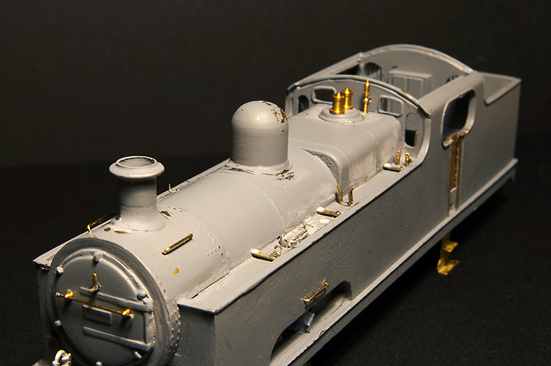 The top of the tanks are vague as supplied with just casting for the water filer caps and 2 air vents that were related to the water pick up gear. In reality only 2015 had this fitted so they should be left off all other models of the class. This is my educated guess of what should be there but i do think there should be more clutter than this. Photos of this area are rare and so far I’ve only found 2
Progress will now need to wait until after Scaleforum where i need some more bits.
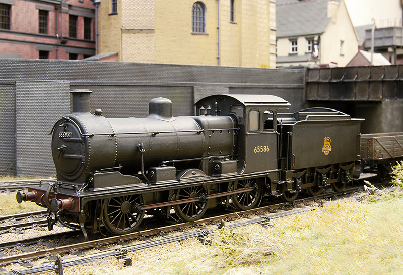
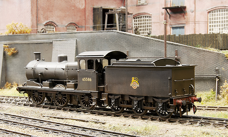
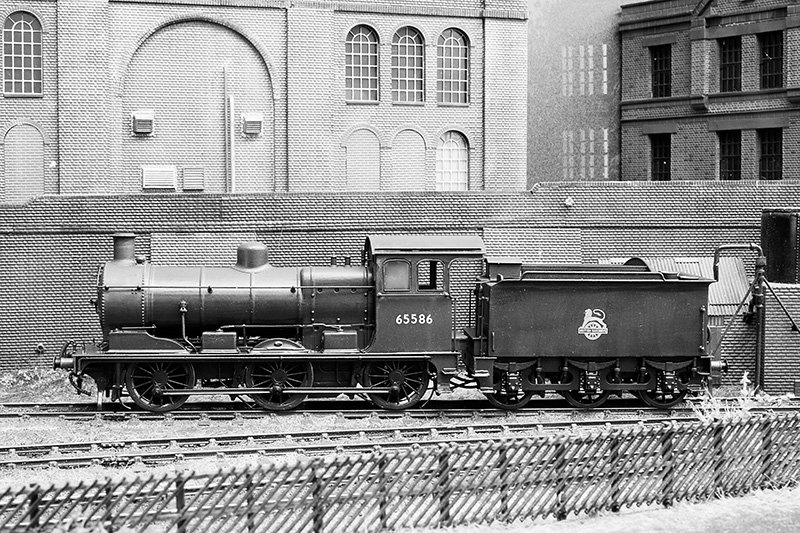
Its all gone a bit Eastern Region – Part 2
Earlier in the year I showed progress on a test build of the Brassmasters J17 kit test build. What follows is progress since then.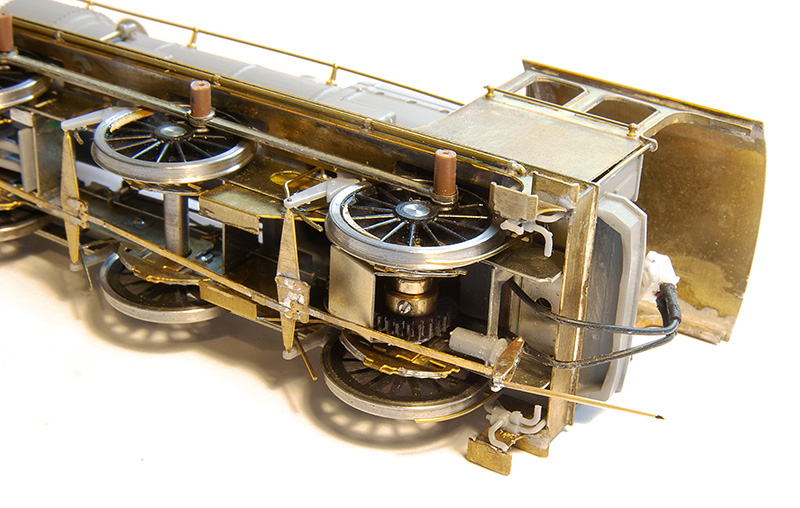
To be fair there wasn’t a huge amount left to do as I left it. One of the jobs was the business end of the brake gear on both the loco and tender. 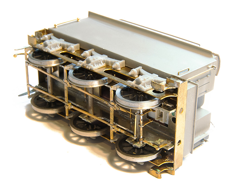
 The other little job on the tender was the guard irons which had been missed off the test etch. These were fashioned up from scrap using a scaled image of the production etch as a guide.
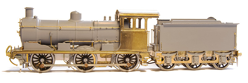
When I showed the side on view before I had managed to get the sanding linkages all wrong. This was subsequently corrected.
(Video © Tim Horn and used with permission) Then it was off to Tim’s for a few days work blocking in the basic greenery on North Elmham which was also an ideal opportunity to give the J17 a chance to stretch its legs. It was unweighted at this point except for a few pound coins in the tender. Attention then switched to getting Brettell Road ready for Scalefour Crewe and besides I thought it would be good for the loco to be displayed on the Brassmasters stand in the raw so to speak. However since then it’s now been finished off with the exception of a crew and some coal in the tender.
For part one of this little project click here
Post Scalefour Crewe reflection
Scalefour Crewe was an excellent show in my opinion and feedback from my operators was that they all enjoyed themselves (thanks for your help guys). Thanks to the show organisers for inviting us. The layout seemed well received and many people were kind enough to say nice things about it. We seemed to be quite successful in holding people attention throughout the weekend.
As with any outing theres aways a period of reflection on how the show went. The layout seemed to fight us a little in the morning but settled down. The main issue being the cassettes were causing a few problems.
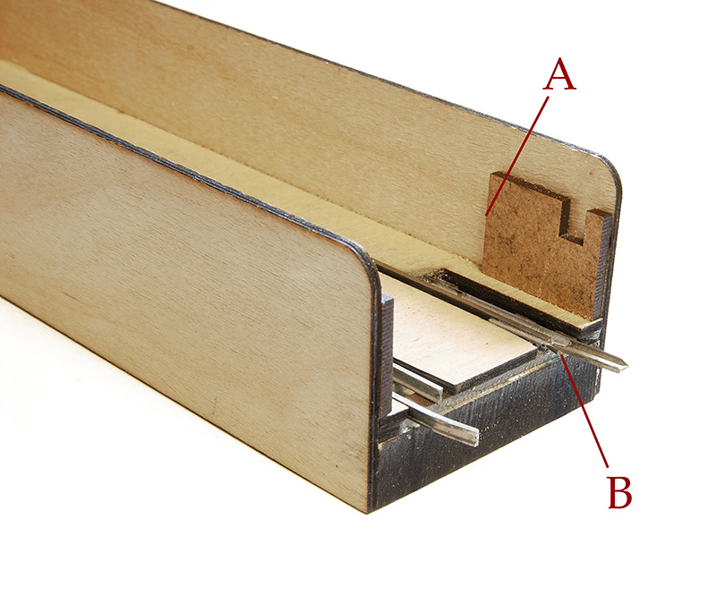 There were 2 areas with the cassettes that need addressing. Area A is that any stock that wasn’t on the rails would strike the edge of the end stop supports and bring the whole train to a halt. It’s unrealistic to think that everything on a cassette will always be on the track 100% of the time as the cassettes are moved around. Thats the point of them after all.
Area B is an easy fix. Theres a bit of wire that holds the connecting rail (which is loose at the end) in line with the rail on the cassette and agains the guide rail. These bits of wire were too straight meaning the joining rail could go the wrong side and all the stock would fall off. A little more of an angle to the wire will solve that.
 First approach to fix problem A was to shape the end supports so that stock doesn’t stop when it hits it. A few trials showed this to be effective but it merely gets the stock past the ends and it still stays off the track. Plan b was to make a re-railer from 30 thou plasticard so that any errant stock is pushed back on to the track. The advantage of this is that I don’t need to reshape the end supports at all as the stock is on the track as it runs off the cassette. This is just a rough proof of concept of course but if I fit one to the end of every cassette, as wagons will need to run of their own cassette and through the loco cassette that gives 3 opportunities to re-rail any rogue wagons and if they are still off after all that then they deserve to go back in the box for attention back home!
Above is a little test video. The brake van is running along the edge of the cassette before the join.
Aside from the usual small stock of wagons that need attention either through failures or just a general refusal on their part to play nicely we had a few issues taking stuff in and out of the yard. There were also a few clunks when running through the slip which is a dead giveaway that something is not quite right somewhere. So on returning home and when I had just 2 boards up, allowing me better access to the slip this has been investigated, tweaked and one of the check rails replaced.
A Bachmann brake van (straight wheel swap, no compensation) does the testing.
Artistic licence
This weekend I was helping Tim at Railex (helping in the loosest term – I was there anyway!) and had a very interesting chat with a chap about lighting on layouts. He explained that lighting is what he does and he was obviously somewhat of an authority on the subject.
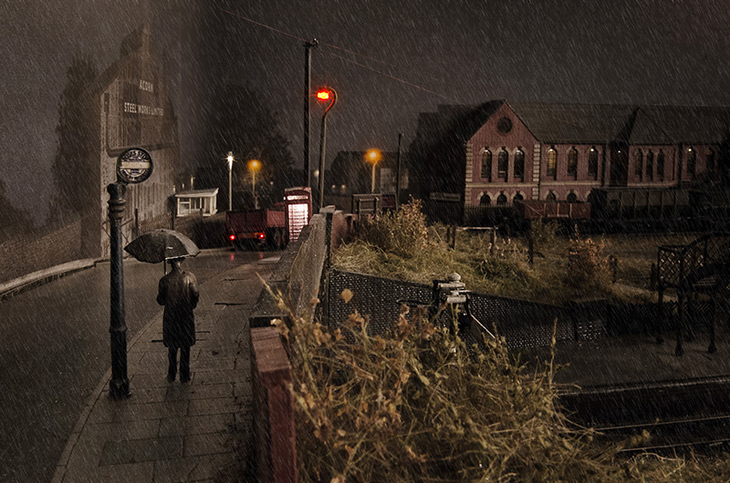 Anyway the subject of this image came up, Apologies for posting it again, I get people are probably sick of seeing it but I have added a bit of rain as some people asked for it. He explained that sodium lighting on a scale of colour gives a very high spike in the yellow range and doesn’t output any other colours. For this image to have the colours it does it would need a white light source, I cant say its the moon because its raining! It actually does have a white light source as I have a string of dim-able LEDs on the wall of the shed that I use to infill my night pictures. He very obviously knew exactly what he was on about! People may have noticed that at night we sometimes see in black and white. It was something I was already aware about on a very basic level. Cameras are much better at picking up colour in low light than the human eye as anyone who recently saw and photographed the northern lights probably noticed.
So I could say that the above image has a certain degree of artistic licence to it. Or at least I could if it was deliberate but the reality is it wasn’t. I hate it when people throw the term artistic licence around to justify missing something or some sort of mistake after its been pointed out. It’s OK to miss things, just don’t try and claim it was deliberate after the event.
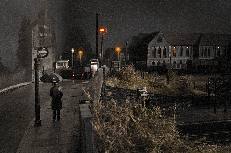 So by taking all of the colour out except yellow (and putting some back in for the lorry lights and inside the phone box) we have an image that more accurately depicts what you would see if you were really standing on a rain sodden bridge in the Black Country at the end of the 1950’s. Two questions now though, The first is which of the two is actually the more pleasing, or nicer image? and the second is anyone actually bothered?