shuffling and testing.
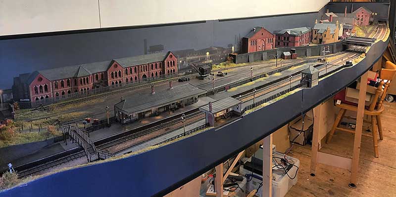
A bit of re-jigging of the shed means I have been able to put all of the scenic boards for Brettell Road up together. Its 5 months since the Cradley show – Time flies doesn’t it?
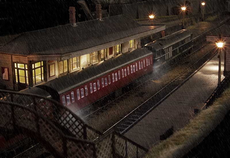
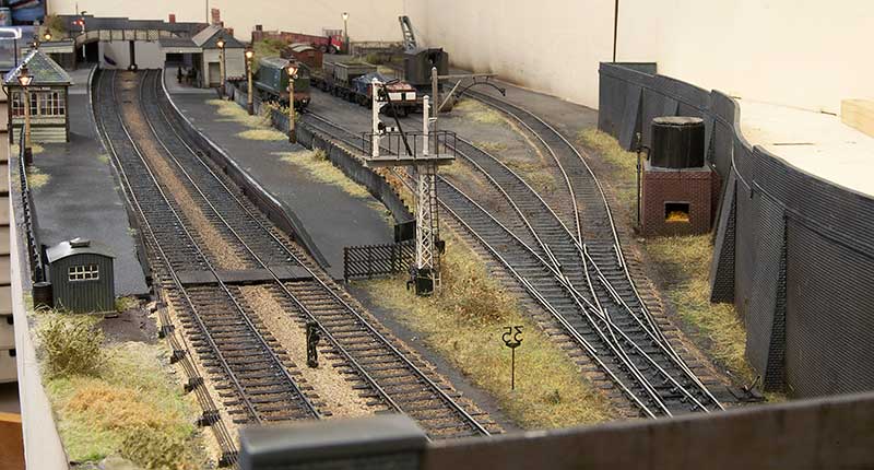
Theres a few things to fix after the show. A couple of the points needed a check over as they weren’t totally reliable. I also found 2 dead sections that hadn’t shown up during the show so I fixed those too. 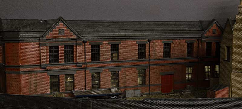 The lights on the upper floor of this building failed before the show but after the building had been planted onto the layout. It was too close to the show to fix it before so this is something to look at now I have time. I also want to add a few yard lights and sort out the telegraph poles on the layout because as they stand now they don’t make a huge amount of sense.
The other thing to fix was the route setting on the main lines. Signalling purists are advised to look away now! Before the track and signals were all operated separately via the throttles with only the yard set up as a route. (My Digitrax system allows me to program routes into it.) So thats been changed for operator convenience so that throwing a signal sets the route as well. I know the route should be set then the signal pulled rather than this way round. You can set the signals to danger on their own but in case you forget the routes will set all the other signals to danger for you anyway. I hoping this will be pretty simple to use.
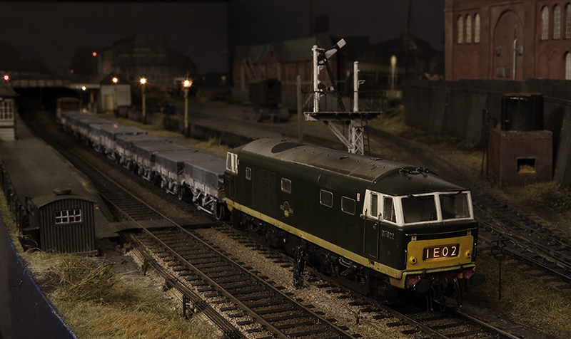
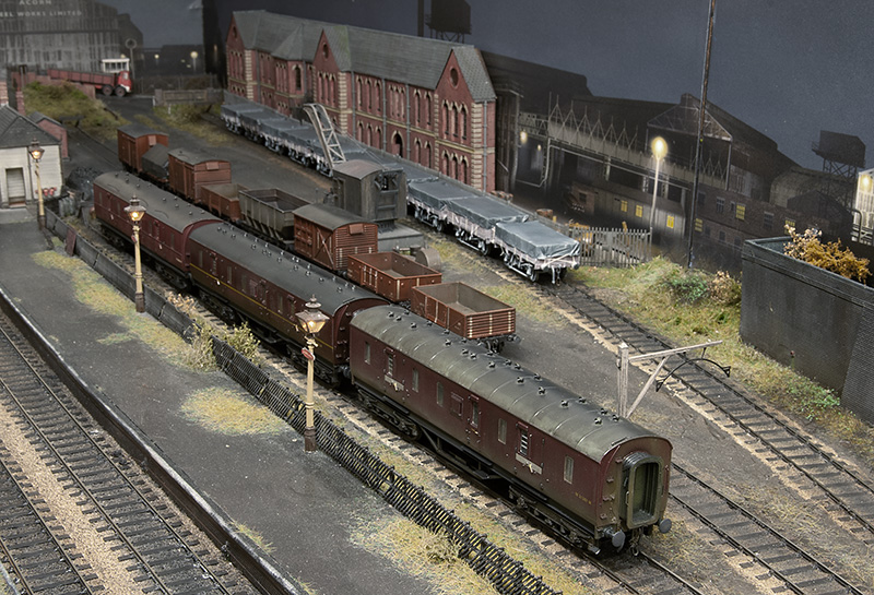 Since the show I have a small stockpile of new rolling stock to be tested. The rule is all stock must go everywhere without falling off, even though in this image only the middle road of wagons will go into the yard at shows. Of this little lot only 4 wagons were rejected and returned to ‘works’ for some fettling. These 4 have now been passed too.
Below, just some more traditional layout style pictures. 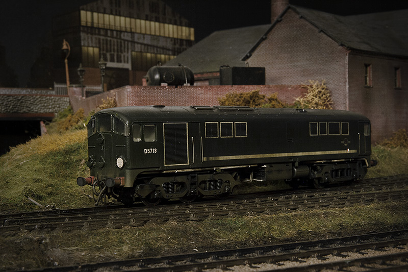
31st March 2023 – A very interesting day.
The 31st of March 2023 turned out to be a very interesting day.
The initial minor disappointment of George, The Stourbridge Junction station cat, being unaccessible for some fuss (he was perched on a filing cabinet at the back of the ticket office having a wash) was quickly tempered by this turning up!
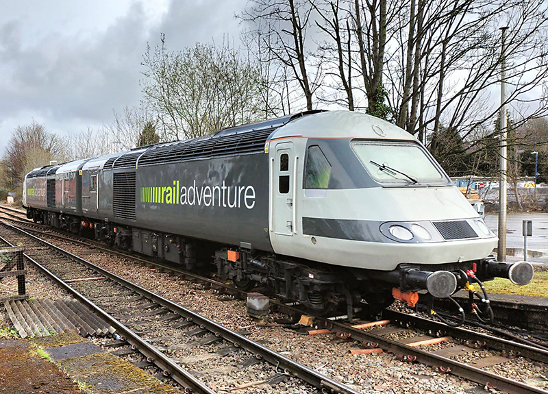
This wasn’t what I was out for mind you. The main event was a tour of New Street’s signal box which you may know has recently been decommissioned. Network Rail ran a ballot for people to have a look round and having been unsuccessful with that my visit was saved by my friend Tom who had a spare ticket.
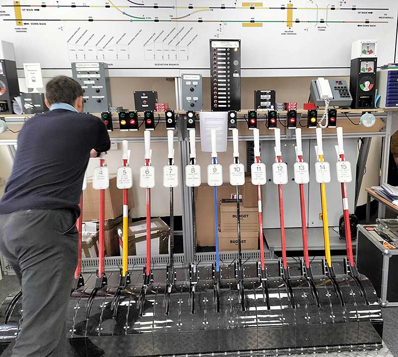 I wasn’t expecting to find a lever frame but there is one. Its located on the third floor which is used for training.
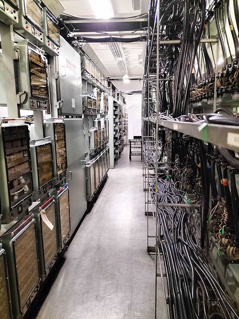 The fourth floor is a gigantic relay room. It still had that lovely electrical machines smell.
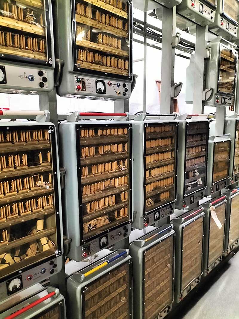 These are called K packs and each one controls 1 thing outside in the station. Theres no plug in a laptop and diagnose a problem with these things. If something goes wrong an engineer would need to use their knowledge of which pack is causing the problem, lift it out and use and the paper schematics that are kept on the same floor to fix it. All under the pressure of something on the station being shut down and the general (organised) chaos that would ensue. We were told that some of these pack have never been touched since the day they were installed. About 60 years of reliable service!
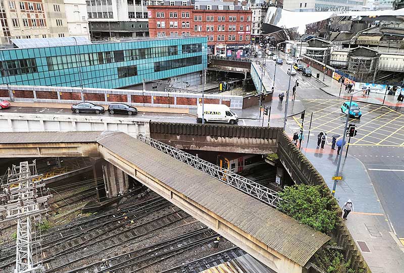 The view from the fifth (top) floor window. The Building directly ahead is about the only thing thats unchanged since my version of New Street set in the late 80’s. The blue building stands where the original lamp block stood and is still called that.
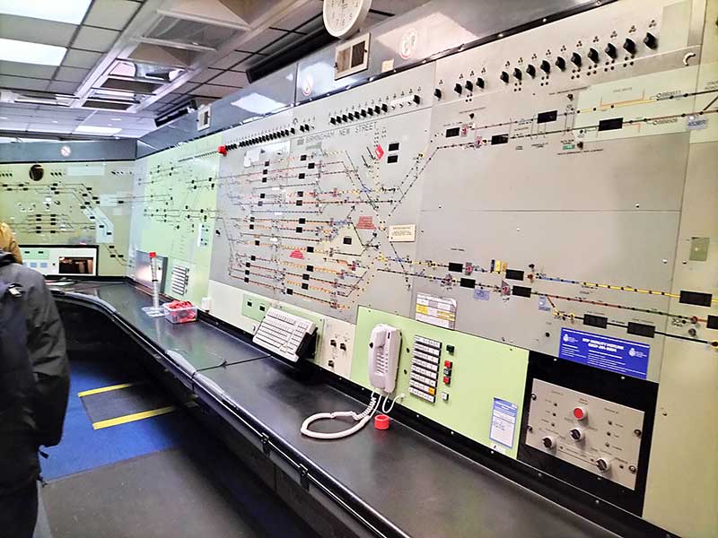 Finally the panel. Who knows how many millions of movements were controlled by this in its lifetime? All the platforms are bi-directional and all worked via permissive block working. Everything being safety netted by the relay room downstairs. We were told it would take a signaller 6 months to become proficient in using the panel although there was one guy who learnt it in 8 weeks.
It genuinely is mind blowing! Thanks to the Network Rail Staff who looked after us all.
Years end – more fiddly bits
As 2021 draws to an end I’ve been doing some of those fiddly little jobs that I kind of hope always get lost into the scene but I know they are there. 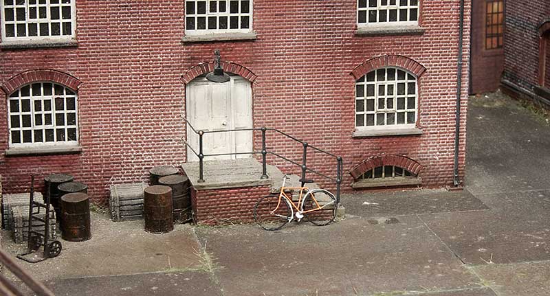 Starting with a pushbike from the Southwark Bridge Models Kit. The kit is for a late 19th century bike so I modernised it a little. I think these may be reduced from 7mm scale model as some of the parts are at the very limit of what will etch and gives you a decent idea of what it must be like to try and solder a spiders web together!
 I’ve finished off the signal wires using MSE posts and easyline.
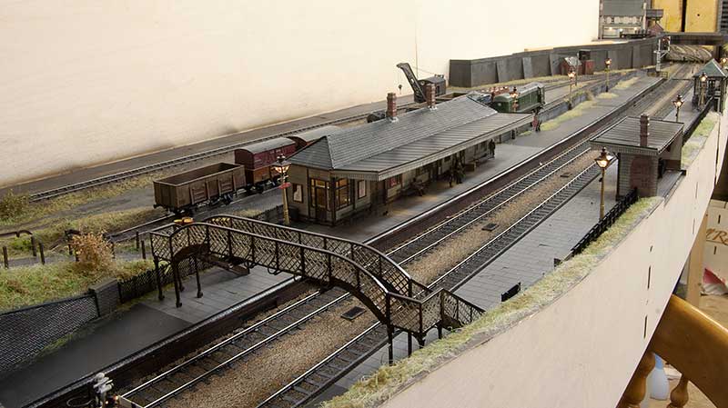
 This meant I could finally get the barrow crossing finished too.
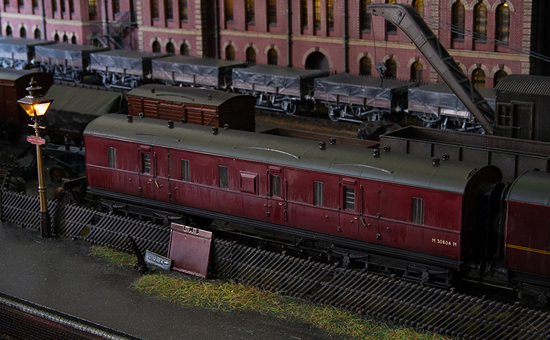
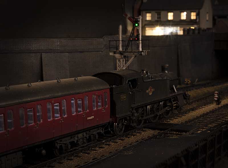
 Below are a few evening shots of various comings and goings.
A dash of autumnal weather.
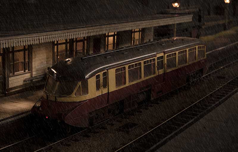
After much experimentation on Brettell Road part 1 and coming up with a working formula. Adding rain to part 2 was a much simpler process (although still a bugger to photograph mind you!)
 View from the middle looking towards Stourbridge. The method I have settled on is to spray everything that needs to be wet with a fine coat of Tamiya smoke. When dry a coat of AK interactive wet effect is added and thats really it. Simple enough now but it took an awful lot of faffing about to get here!
 View towards Dudley
 This is the view from the old layout to the new one . While its not something I intended to capture when I took the picture it does show the elevation changes quite well.
Below a few evening pictures
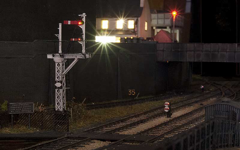
Signals
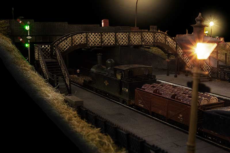
I think I may have mentioned before but one of my favourite things on Moor Street is the mechanical signals. Obviously on New Street there was never going to be an opportunity to do any but on Brettell Road things were different. I had already built a few ground signals on part 1 and an abandoned one but part 2 has given me the opportunity to do some proper, working ones.
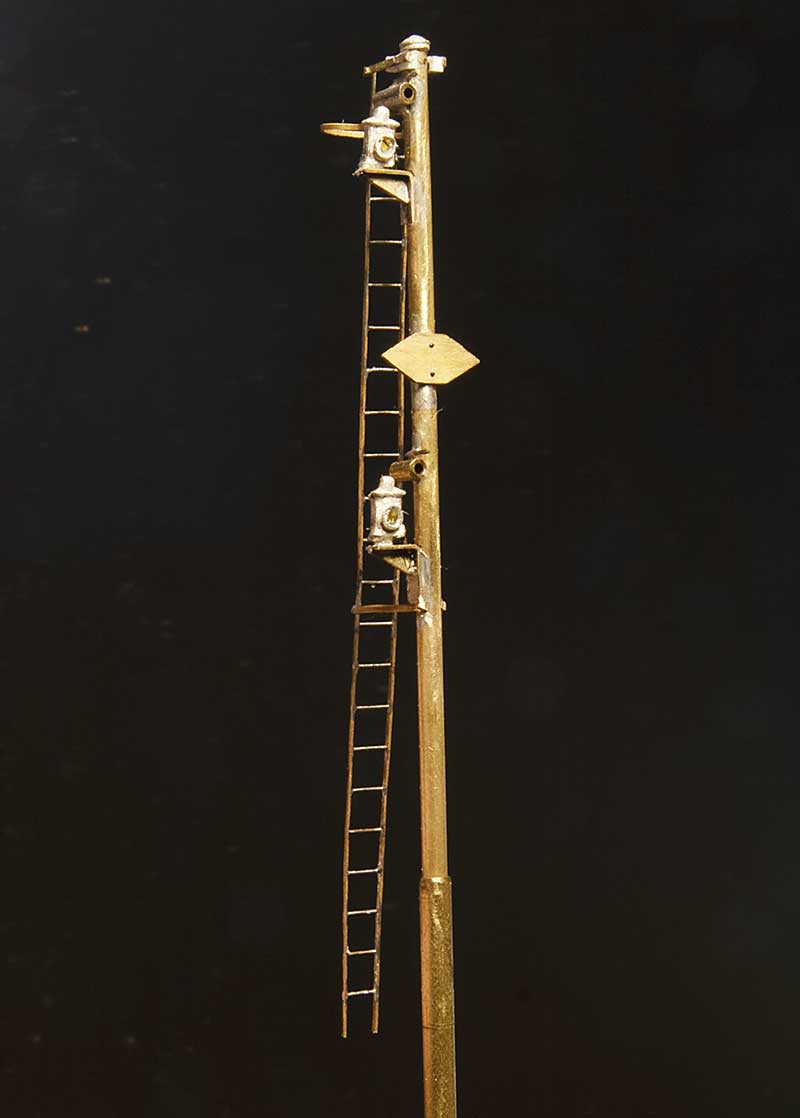 So starting with the post for the simple one. Basically a bog standard upper quadrant affair only complicated by the need to have a co-acting signal due to where the signal stands in relation to the footbridge. The balance weights are below the platforms surface. The parts used are the MSE upper quadrant signal parts (S0012/1), LMS/LNER tubular post caps (SC0019) and LMS Adlake signal lamps (SC0011). The Ladder is from Stenson models and various diameters of tube, sized from the left overs from the signal I built before. This will sit at the Stourbridge end of the platform.
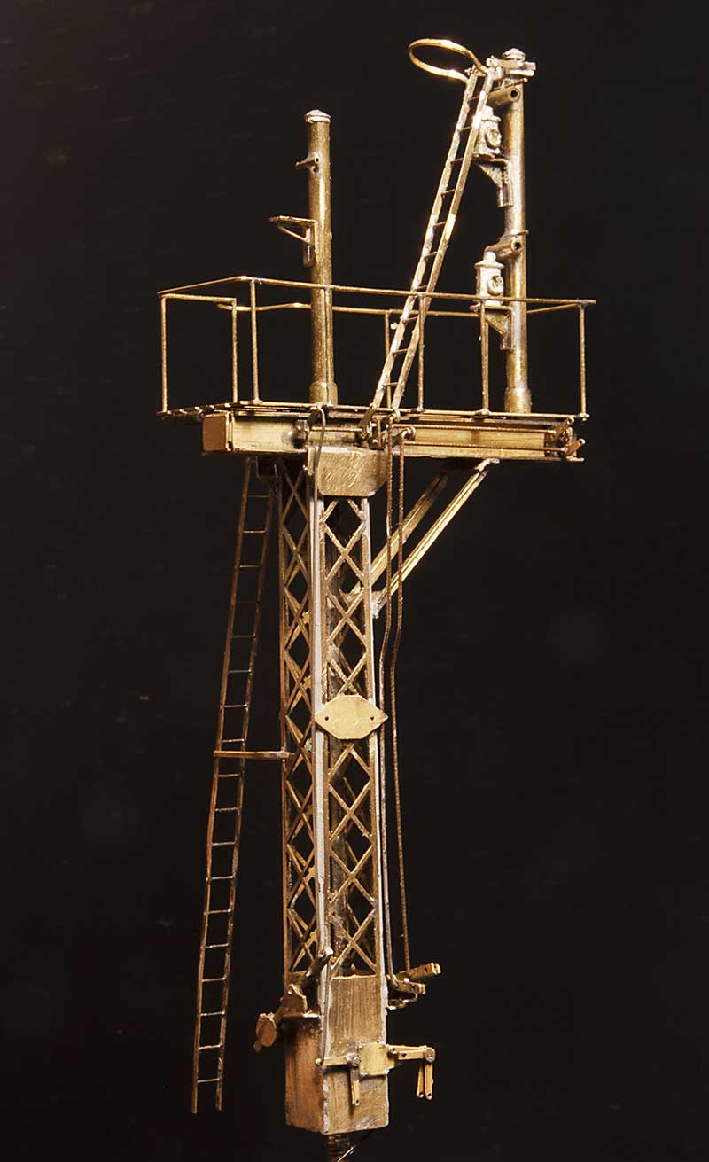 At the Dudley end things are a little more entertaining. So having found a suitable victim (which turned out to be a bit of a mongrel) I set to work emulating what I could see. More MSE bits such as Heavy Lattice Bracket Signal Base Post (S0010) and LMS welded stem bracket (50029) for the platform. The rockers came from the Brassmasters point rodding etch. After I took this photo I decided that the operating ‘wires’ were too big so they have been replaced with no8 guitar strings.
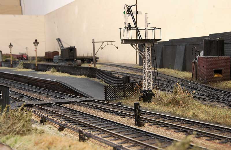
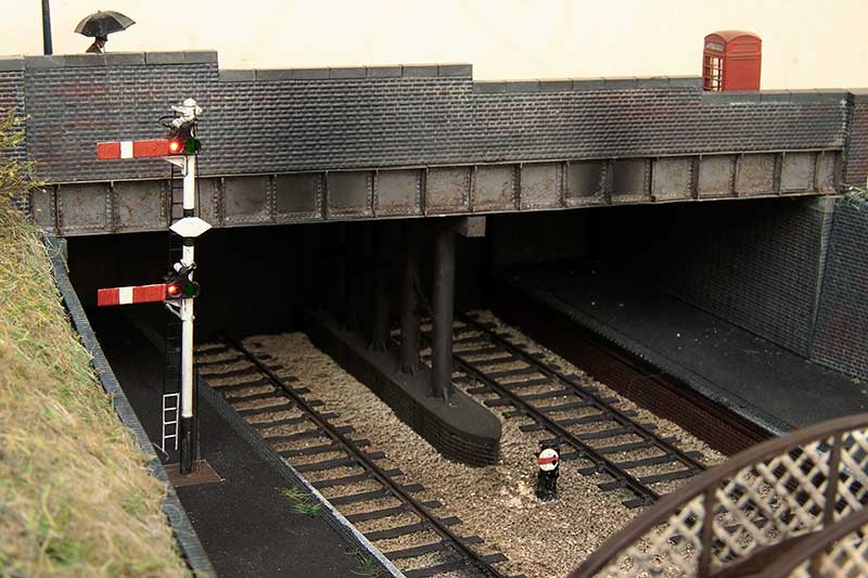 Platform starter in position.
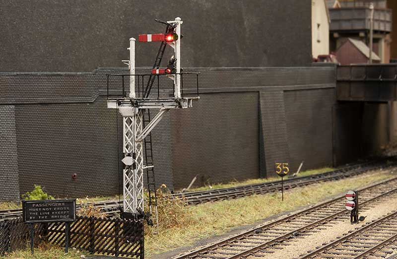
Gantry in position. The left arm was used for the Kingswinford branch (now disconnected)
Nothing new here
 With the point rodding redone and signal wires back in place theres not really anything left to do on Brettell Road part 1. I was hoping to embrace the latest technology with the rodding and decided to go with 3d printed BR stools from Modelu. However those didn’t work out for me at all and proved to be far too fragile. Ive sent them all back and Alan is going to investigate as he believes there was a problem with the resin. I’ll do a follow up post when he comes back with his findings. So as the old adage goes, sometimes its best to stick with what you know I went back to the trusty Brassmasters etched ones instead.
 The cranks are also Brassmasters although I’ve used the MSE bases as I thought they were better. The rodding itself and signal posts are also from MSE with the signal wires from ezline. Unlike the previous version where I made some of the point rodding work, just to see if i could, I didn’t feel any need to to it again.
 A few more detectors for the ground signals were knocked up from bits of brass and my rain technique of coats of Tamiya smoke and AK wet effects fluid reapplied. I guess you could say I’m back to where I was a few months ago!
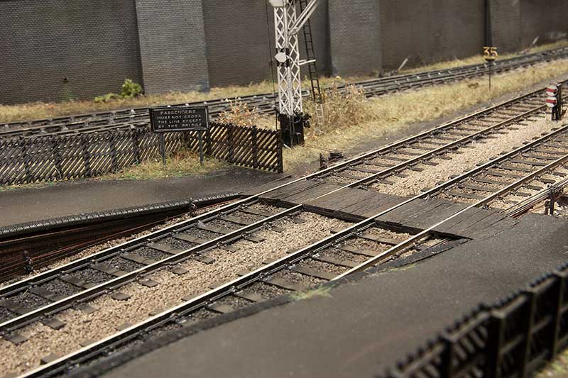
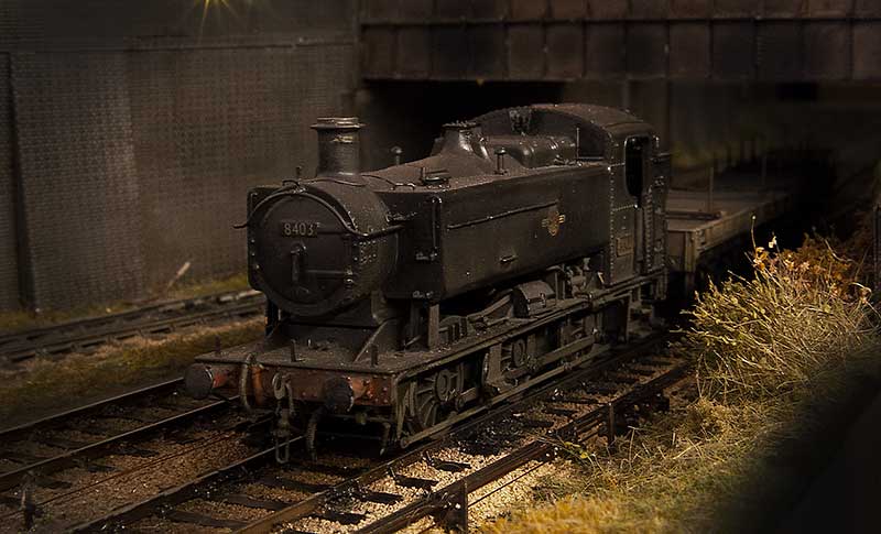
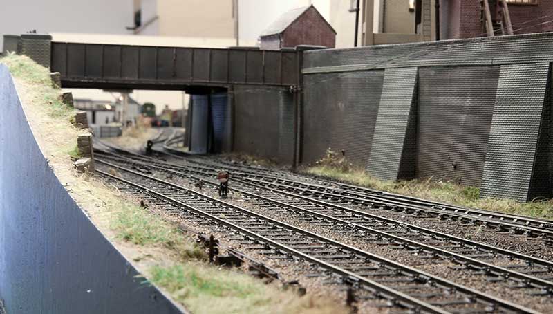
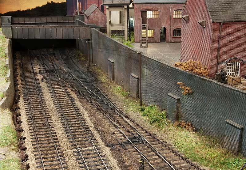
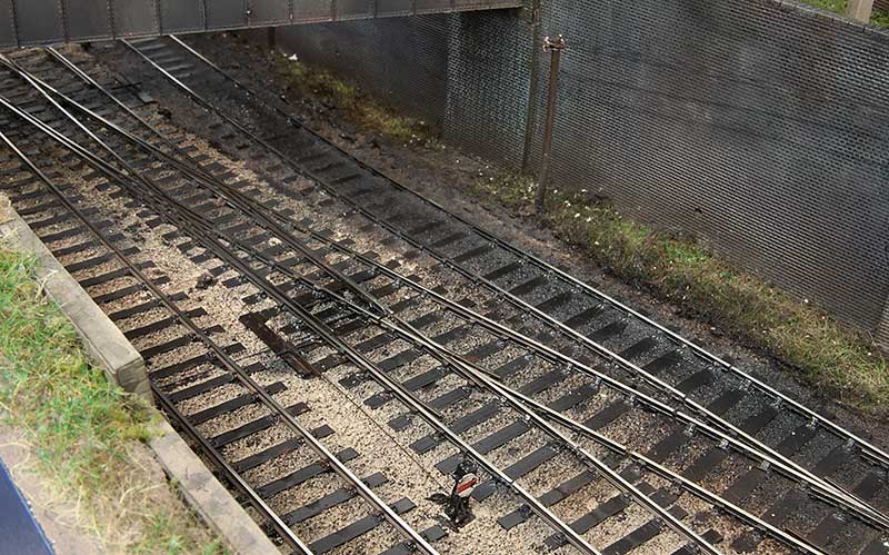
 Theres something oh so familiar about glimpses of grubby track between bridges and retaining walls.
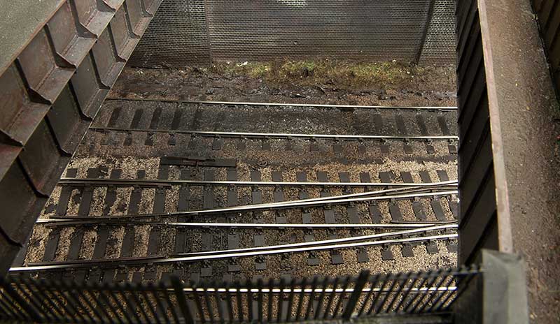
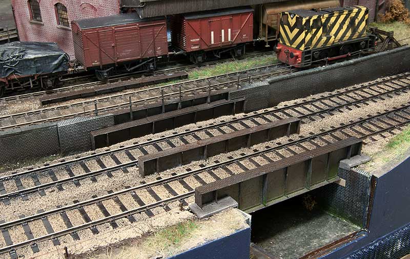 At the other end of the layout the extra bits of the bridges have been added.
 One thing I forgot to mention before is this stuff. Its great for fixing ballast and while its no where near as cheap as the traditional PVA/ water/ washing up liquid concoction it can be used straight from the bottle with no messing around wetting everything first.
Wires and signals
Part of the process in upgrading Brettell Road and preparing it for part 2 was to redo the wiring. Those that have been following from the start will recall that it was initially only a plaything and not an exhibition layout and the wiring reflected that being just 4 wired between boards. 2 for the DCC and 2 for the AC supply. A concession was made after the first show to provide short protection for each board but its not really how things should be done so its been mostly stripped out and done again.
So now the DCC is split into 3 sections. One for the yard, one for the mainlines and one for the accessories. Theres little point having short protection if said short cuts off the ability to throw the points and resolve it. The AC is also split into 2 sections as well, the second being a DC supply for LEDs. You can use AC for LEDs anyway but the flicker can be noticeable sometimes. So now theres 10 wires between boards instead.
Signals
The new arrangement for entering the yard has required a few new signals as well.  Mainly a couple of ground signals from the MSE kits. I need a couple more for part 2 (one of which is a double) so I built them all together. these are powered by servos controlled by a Tam Valley control board.
  I guess this also comes under signals? A simple limit of shunt sign from a MSE lamp a bit of brass tube and some microstrip.
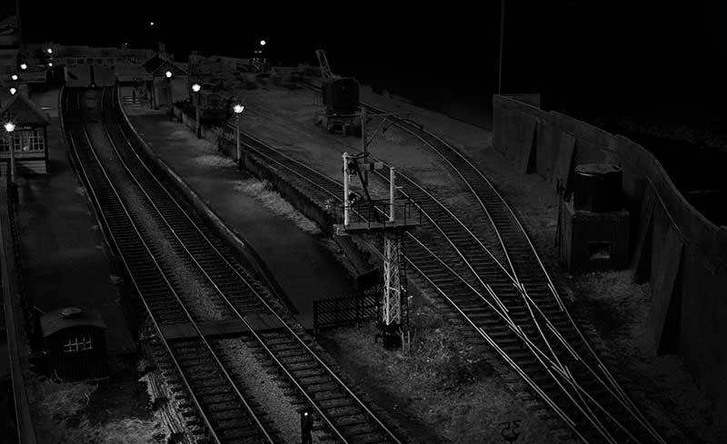
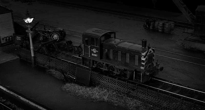
Below a couple of mood shots .


Soldering on
I’ve had an enjoyable few days soldering stuff. Not random bits of brass to make bits of overhead but proper kits, designed by someone else!
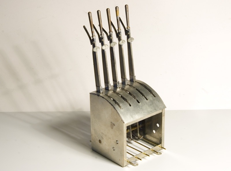
Starting with this rather nifty lever frame from the Scalefour Society. One of these can often be found on their stand at shows and it’s pretty hard to resist having a play with it. At one point I thought of getting one just because it’s nice! Now with Brettell Road I have an excuse!
It’s build as per the instructions. The kit allows for additional micro switches to operate point motors but in this case I’m planning a purely mechanical system.
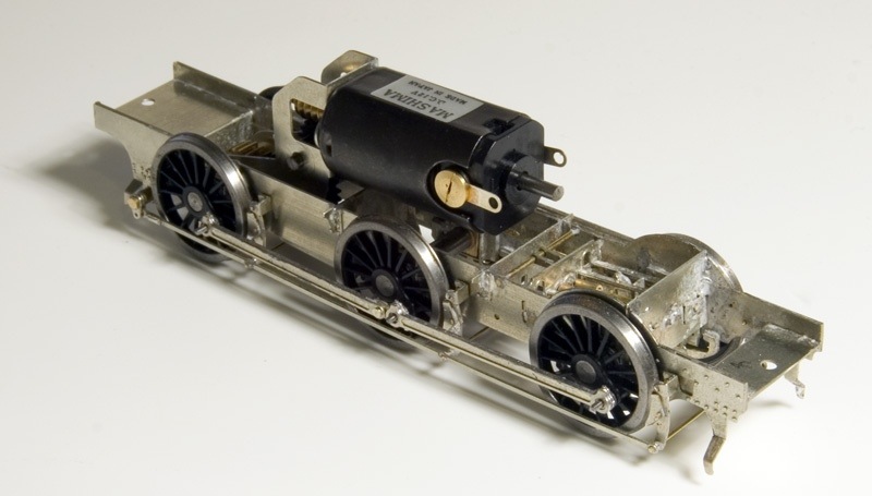
Next up the High Level chassis kit for my Jinty. As supplied the kit is designed for traditional compensation but I wanted mine sprung. The current fad for continuous springy beams seems like a lot of faffing about (I admit I’ve never tried it) and doesn’t really replicate what I see on real locos. The idea of equalised beams seems a whole lot more simple, uses less bits and is what the real thing does, (ok not a Jinty but think of a class 47 bogie).
Other than that I followed the instructions and for my first ever etched chassis I was surprised that it only took 2 afternoons to get it all together, I’m not sure why I thought it should take any longer to be honest. Obviously there’s a bit more to do yet, balance weights and pick ups.
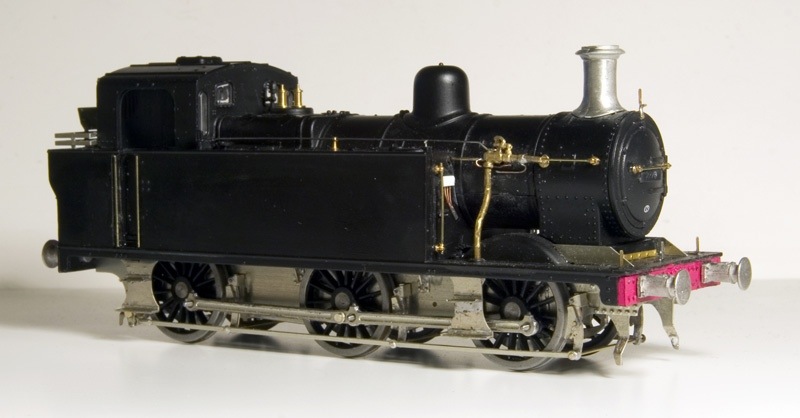
Above a quick mock up of how it all looks. The steps don’t come with the kit and are from the Brassmasters detailing kit I used earlier. It’s something a bit different for me and it’s really nice that someone has done the thinking about it stage for you. Makes a change from assembling a load of unrelated bits and having to figure out what to do with them!
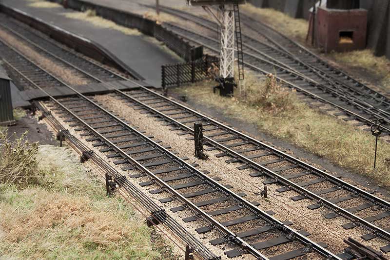
Point rodding and hints of the past.
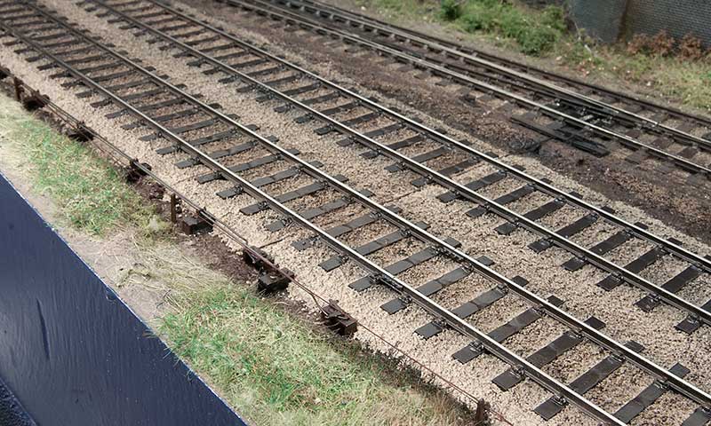
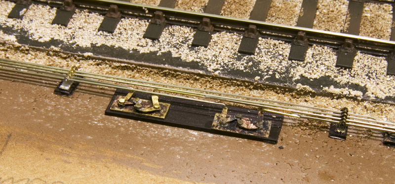
What you see above is a representation of a detector for the ground signal on Brettell Road. It was knocked up from scraps of brass using photos and Steve Hall’s articles in MRJ 113 and 115. I always enjoy fiddly details like this even though I know it will go unnoticed to most people.
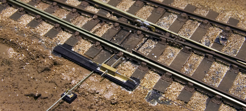
There’s only going to be 1 point on Brettell Road that’s operated by the off scene signal box, the rest being operated by hand levers. However I wanted to include remnants of what was there before meaning the double slip would have been operated either end with facing point locks. Also given the distance a couple of compensators will be needed so while it’s not exactly complicated stuff it is worth doing.
My chosen route is the Brassmasters etched bits with rodding from MSE. I have also included the odd rodding stool where the rodding has been removed to help with the idea that it’s not so much added to the layout as taken away.
Most of this stuff is quite basic if a bit fiddly. Above are a couple of compensators. The ones supplied are cosmetic and don’t move and that’s fine for the disused rods as per the one on the right however with only 1 run that does anything it would be rude not to make it work. Ok it’s driven from the point rather than driving the point itself but let’s not worry too much about that. 2 Brassmasters compensators were used to make the one on the left with the centre arm from one and a few brass pins meaning it will move when the point it thrown.
All in a fun little project.
http://www.youtube.com/watch?v=5QrJsLczids&w=600
Signals
I’ve always liked mechanical signals, the ones on Moor Street are great fun to play with but for New Street I wont get the chance to have any. However for Brettell Road there are 2 (one of which is abandoned) so I have got to have a go at making some from MSE kits.
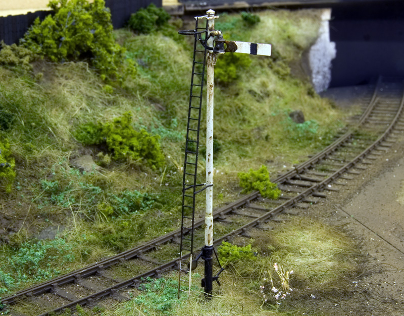
First up the disused one, based on a photo I found. This one would actually be a repeater for the main signal the other side of the bridge due to sighting problems. Weathering is done with gouache. I replaced the supplied ladder with one of Colin Craig’s.
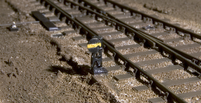
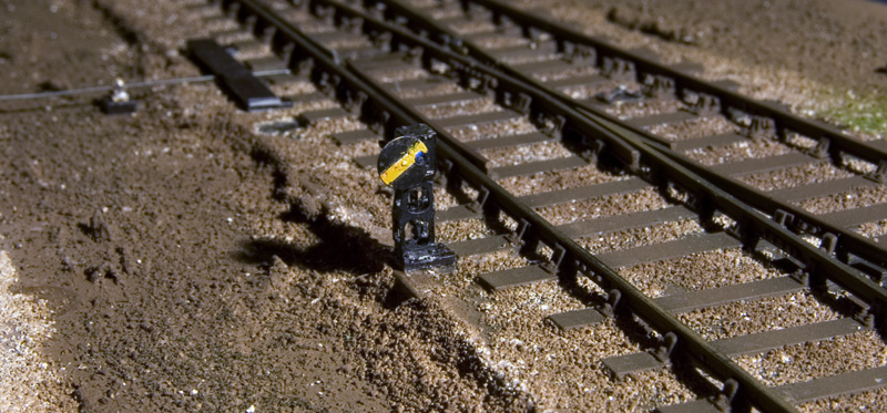
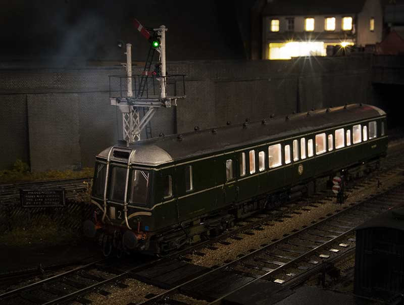
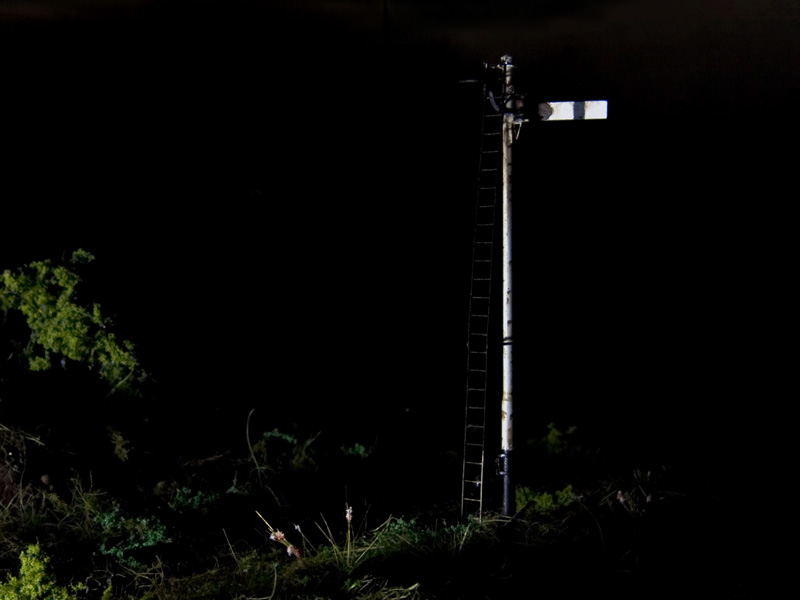
The other signal is this little ground signal (yellow so that the headshunt can be used when its set to danger) I deviated from the MSE instructions by making the counterweight arm work too. Theres a fibre optic in the lamp but its a bugger to photograph – you can just make it out in the second picture. It looks a bit blue but I was using a white light source – changing it to a yellow one should correct this.
Finally as I was tidying up I left a pack of LED’s lying on the layout and purely by chance it illuminated the signal. Thinking it looked quite nice I took the image below – I’d like to claim it was carefully planned but nope – this was just lucky!
Click here for Model Signal Engineering’s website